
Spare electricity system and method for realizing power supply

An electrical system, dual power supply technology, applied in the direction of electrical components, radio/induction link selection arrangement, selection device, etc. Extend the normal working time, extend the power supply time, and ensure the effect of business capability

Inactive Publication Date: 2006-10-25
HUAWEI TECH CO LTD
View PDF0 Cites 5 Cited by
  • Summary
  • Abstract
  • Description
  • Claims
  • Application Information

AI Technical Summary

Problems solved by technology

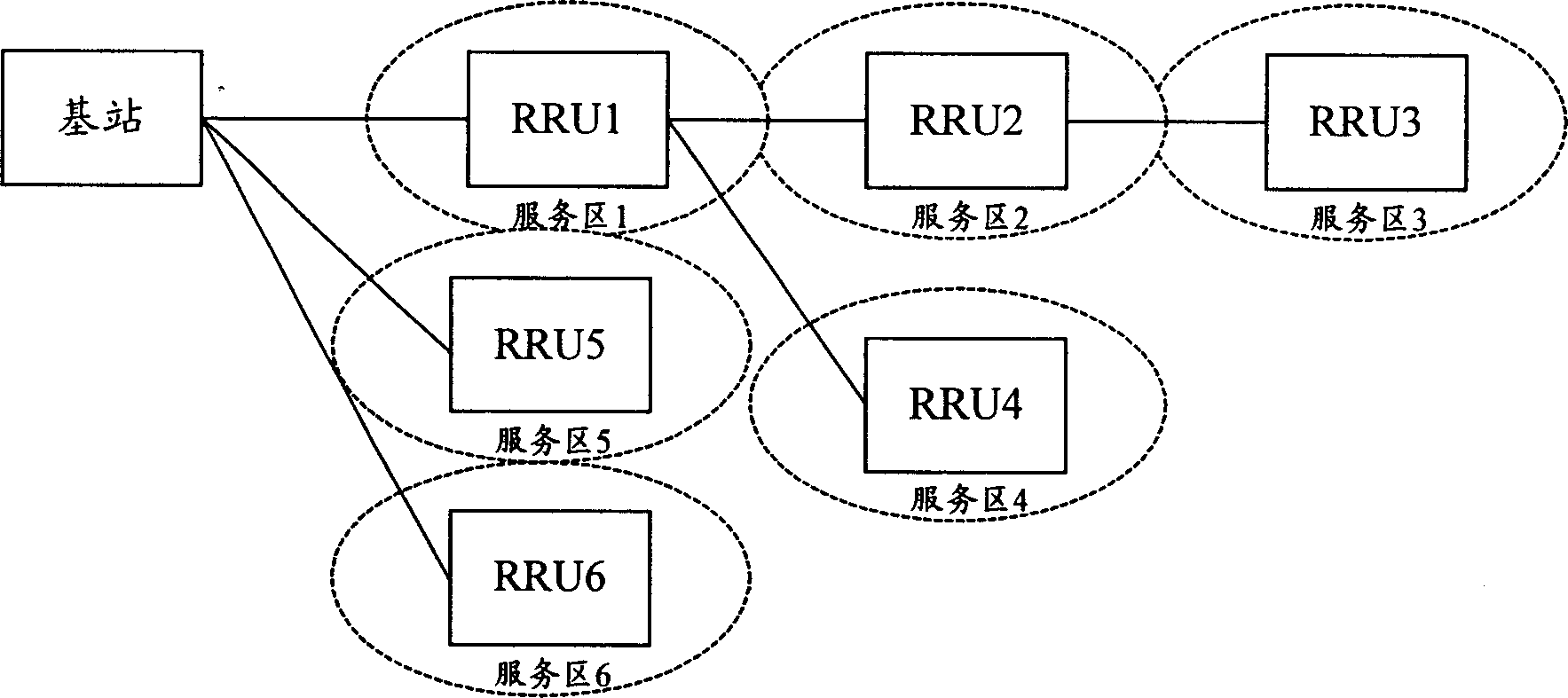
Such processing, when there are large power-consuming modules in the device, will cause the power of the backup power system to be exhausted prematurely, which will cause the device to exit service prematurely, especially for the case where the devices are networked through a chain or a tree. It is easy to cause communication interruption due to the rapid exhaustion of the backup power supply, which will affect the quality of service of the system where the equipment is located

Method used


Image

  • Spare electricity system and method for realizing power supply
  • Spare electricity system and method for realizing power supply
  • Spare electricity system and method for realizing power supply

Examples


Embodiment Construction

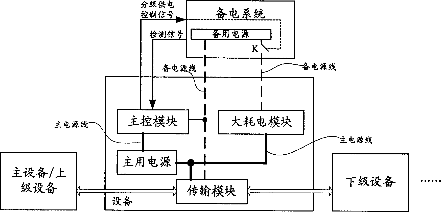
[0041]The core idea of ​​the present invention is: according to the needs of users, control whether to cut off the power supply of the backup power system to the large power consumption module in the dual power supply equipment, reasonably prolong the time that the equipment powered by the backup power system can maintain normal work, and ensure The service capability of the system where the device is located.

[0042] In order to make the object, technical solution and advantages of the present invention clearer, the present invention will be further described in detail below with reference to the accompanying drawings and preferred embodiments.

[0043] Figure 2a It is a schematic diagram of the application structure of the backup power system of the present invention, such as Figure 2a As shown, the dual power supply equipment at least includes a main control module, a large power consumption module, a main power supply, a backup power system and a transmission module. T...


PUM


Abstract

Sending control signal for classified power supply to control switch in backup power system from main control module in power supply equipment of backup system, the disclosed method controls backup power system to supply power for module with large power expenditure in the equipment. Thus, the method guarantees that the equipment cuts off power supply for the module with large power expenditure when main power source is in power down so that the backup power system enters into mode of classified power supply to prolong power on time of the backup power system. According to users' need, the method controls whether backup power system cuts down power supply for module with large power expenditure in order to ensure service capability of system.

Description

technical field [0001] The invention relates to power supply technology, in particular to a power backup system and a method for realizing power supply. Background technique [0002] As we all know, in order to ensure that the equipment can work reliably, the equipment is usually equipped with a main power supply and a backup power supply. Generally, the backup power supply is a battery, which is part of the backup power system. The backup power system can be placed inside or outside the equipment. Such a device may be referred to as a dual power supply device. The main power supply is generally powered by the mains power supply, which is converted into the power required by the equipment and then supplies power to the equipment. When the mains power supply is interrupted due to reasons such as mains power supply failure, the equipment will send a main power failure alarm to the network management center where it is located. And automatically switch to the power supply from...

Claims


Application Information

Patent Timeline
IPC IPC(8): H04Q1/28H04Q7/30
Inventor 余明
Owner HUAWEI TECH CO LTD
Learn More