
Cooling water-tower sprinkling plate structure

A technology for cooling water towers and sprinkler trays, which is applied to water shower coolers, direct contact heat exchangers, heat exchanger types, etc., and can solve the problems of reducing water consumption recovery rate, increasing electricity cost, and discounting the effect of hot water cooling to reduce congestion, save water and electricity costs, and improve industrial competitiveness

Inactive Publication Date: 2006-10-25
宋柏翰
View PDF0 Cites 2 Cited by
  • Summary
  • Abstract
  • Description
  • Claims
  • Application Information

AI Technical Summary

Problems solved by technology

[0003] 1. When the diameter of the water nozzle is large, the sprayed water will be conical and radial, that is to say, the cooling water will be concentrated on the outer side, and the cooling water directly below the water nozzle will be the least. Therefore, this will cause the cooling water to be sprinkled on the hot water pipe rather unevenly, so that the effect of cooling the hot water in the hot water pipe is greatly reduced, which is its main problem
[0004] 2. When the nozzle diameter is small, impurities in the water (because the pumping motor does not have a filter function) are often deposited and blocked at the nozzle, causing the nozzle to be blocked. At the same time, it will also cause inconvenience in cleaning. this is another problem with it
[0005] 3. As mentioned in item 2, due to the small caliber, the sprayed water is atomized, so that the atomized water vapor is easy to be discharged upwards with the ventilation of the fan motor, which will not only cause a rapid increase in water consumption loss, and will also reduce the recovery rate of the used water. At the same time, it is necessary to supplement the flow of new water sources, which will greatly increase the required water consumption, increase the water fee cost of the user, and thus do not meet the current water resources ( That is, the policy of increasing revenue and reducing expenditure)
[0006] 4. As mentioned in Item 2, in order to achieve the atomization effect of the sprayed water, the diameter of the water spray port must be reduced, so the pressure in the water spray pipe will increase, and the motor will be damaged. The load increases correspondingly (because the amount of water discharged is less than the amount of water pumped up), and the power consumption of the motor increases greatly, which will not only cause waste of power consumption, but also increase the cost of power consumption. This is it yet another question

Method used


Image

  • Cooling water-tower sprinkling plate structure
  • Cooling water-tower sprinkling plate structure
  • Cooling water-tower sprinkling plate structure

Examples


Embodiment Construction

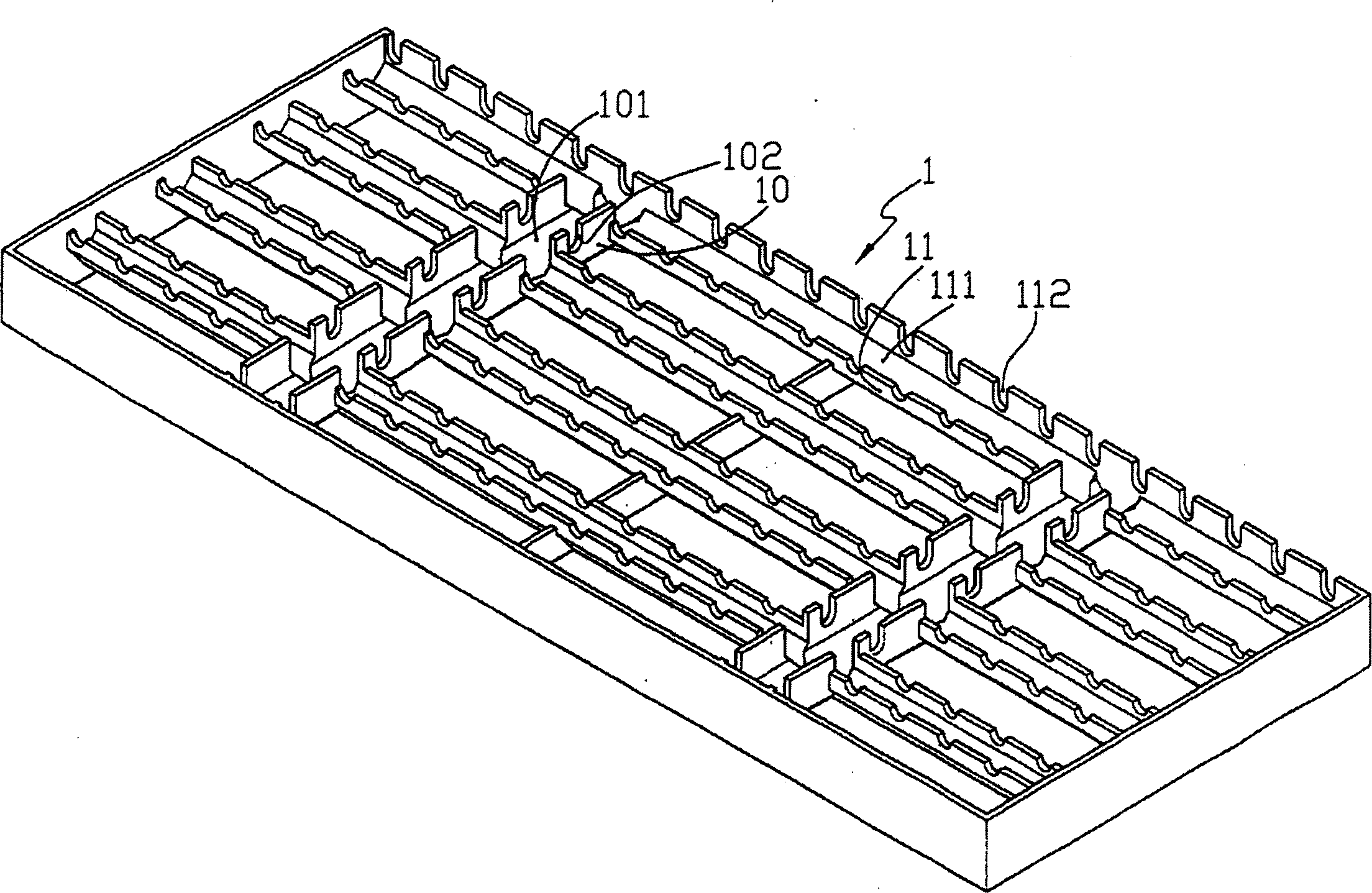
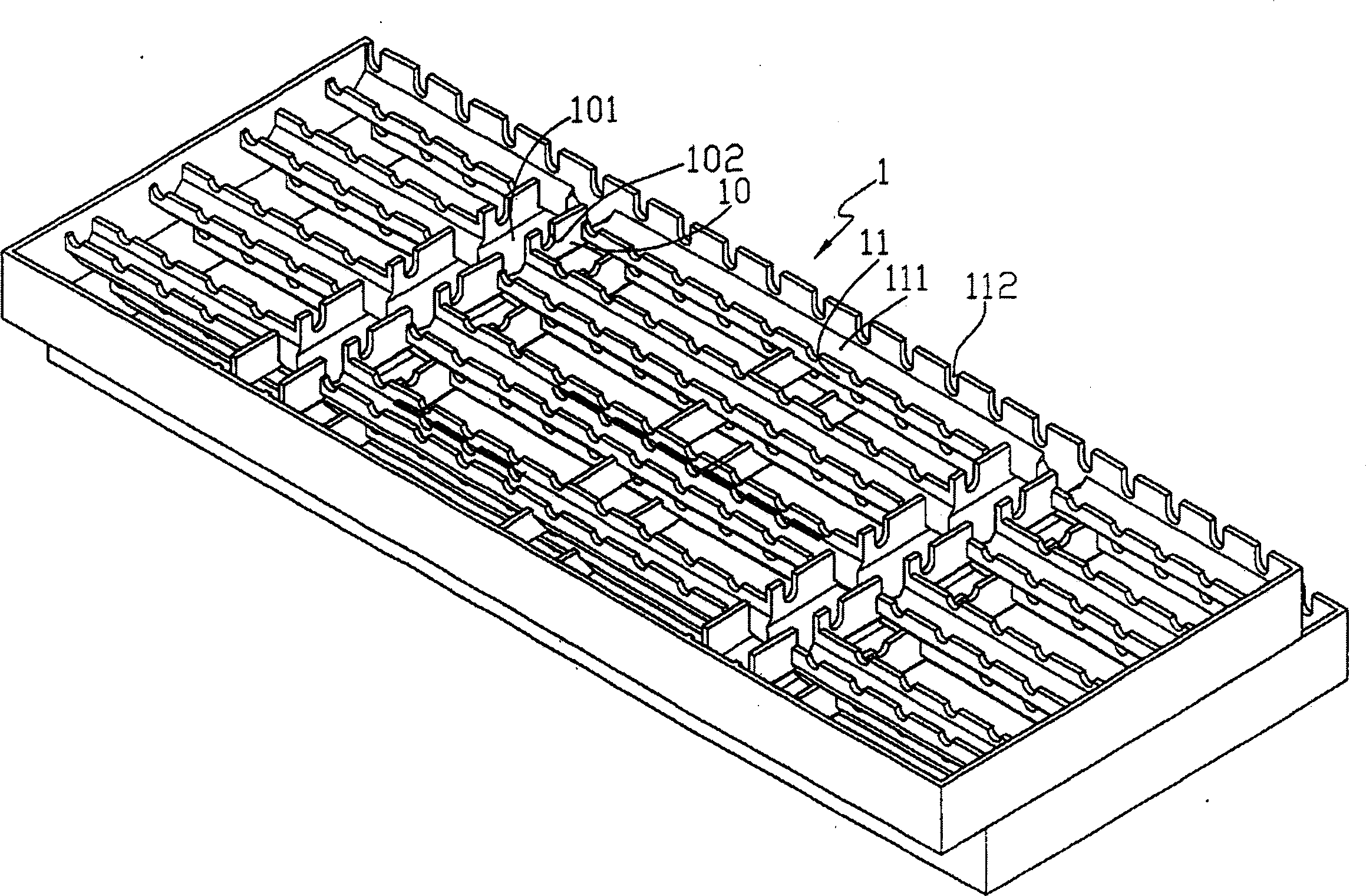
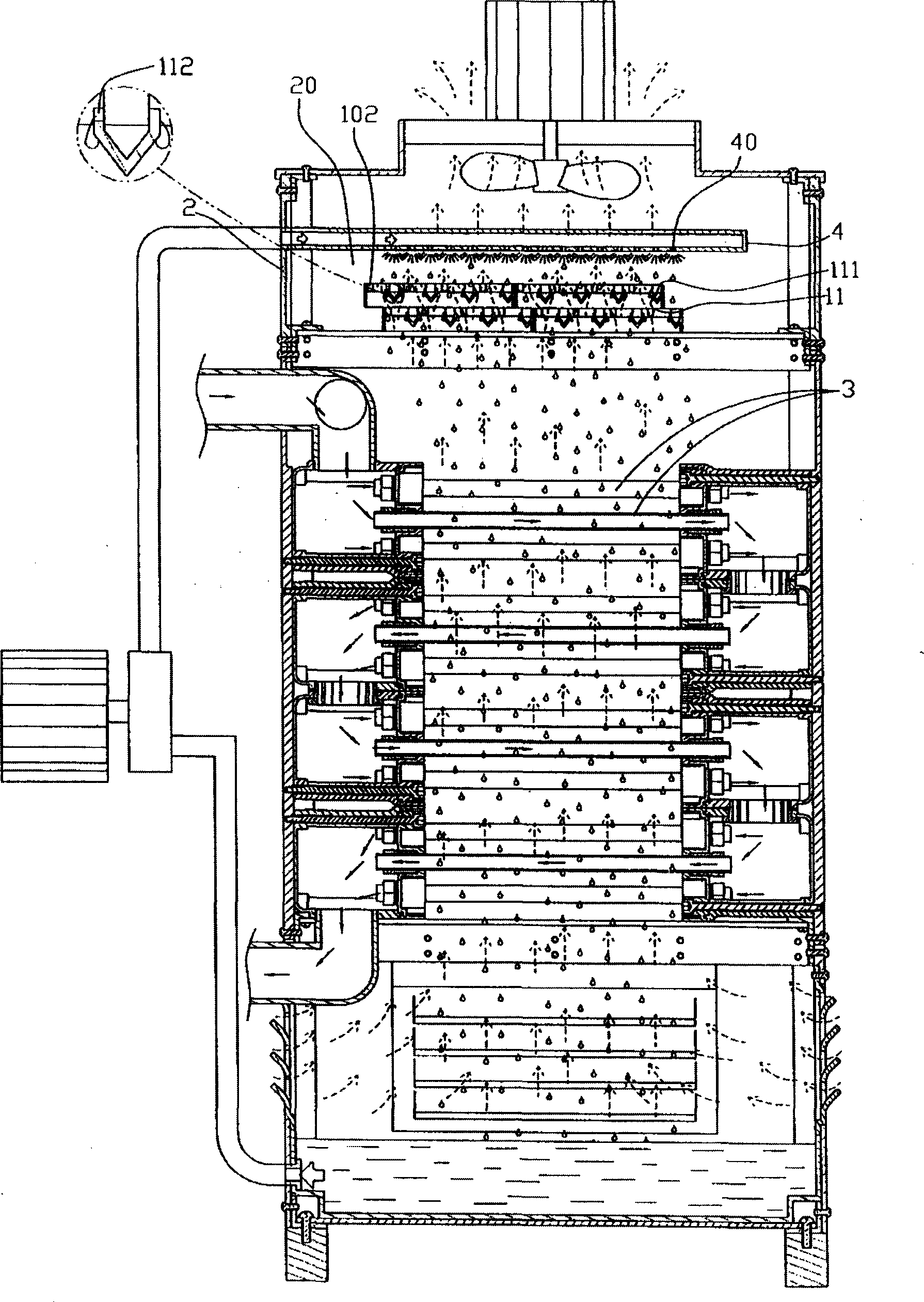
[0019] refer to Figure 1 to Figure 4 , a cooling tower sprinkler plate structure of the present invention, which mainly includes a plate body 1, which can be composed of several longitudinal ribs 10, or composed of several transverse ribs 11, or composed of several longitudinal ribs 10 and transverse ribs 11 are composed of each other, and the two adjacent longitudinal ribs 10 are parallel, or the two adjacent transverse ribs 11 are parallel, or the longitudinal ribs 10 and transverse ribs 11 are interlaced. ; Moreover, flow channels 101, 111 can be provided inside the above-mentioned ribs 10, 11, and gaps 102, 112 are provided on the peripheral sides of the flow channels 101, 111, so that cooling water drips on the flow channels 101, 111 of the tray body 1 After the internal assembly, it can overflow from the gaps 102, 112 to the outside.

[0020] When in use, it is only necessary to stack the two trays 1 on top of each other and then install them at an appropriate place ab...


PUM


Abstract

The invention relates to a structure concerning on cooling water tower aspersing structure, especially the cooling water tower aspersing disc structure. It includes disc identity that is made up of plural portrait ribs or plural athwart ribs or plural portrait ribs and plural athwart ribs. Flowing channel is set inside the rib, and the notching is set at the side of the flowing channel. The benefit of the invention is that it could shorten the cooling time and improve cooling efficiency.

Description

Technical field: [0001] The present invention relates to a structure related to the sprinkling structure of the cooling water tower, more specifically, to a kind of cooling system that can distribute the overflowing water evenly in the cooling water tower, so that the hot water in the water pipe can be cooled surely. Water tower sprinkler plate structure. Background technique: [0002] At present, the commonly used sprinkling structure of cooling water tower is to be provided with a closed pipe body above the water tower, and several water spray ports are arranged above or below the pipe body, and a fixed distance is set between adjacent water spray ports; , although it can cool the hot water in the water pipe, it has the following disadvantages in operation: [0003] 1. When the diameter of the water nozzle is large, the sprayed water will be conical and radial, that is to say, the cooling water will be concentrated on the outer side, and the cooling water directly below t...

Claims


Application Information

Patent Timeline
IPC IPC(8): F28F25/04
Inventor 宋柏翰
Owner 宋柏翰
Learn More