Device for guiding, conveying, or treating a fiber cable

A fiber rope and equipment technology, applied in the direction of drafting equipment, fiber processing, thin material processing, etc., can solve problems such as different loads, achieve the effect of reducing fiber transmission, reducing risks, and simple operation

Inactive Publication Date: 2006-10-18
SAURER GMBH & CO KG
View PDF1 Cites 14 Cited by
  • Summary
  • Abstract
  • Description
  • Claims
  • Application Information

AI Technical Summary

Problems solved by technology

[0003] However, the problem that arises in this case with multiple rollers is that the physical relationship (Eytelwein's rope friction formula) results in different loads on the rollers

Method used


Image

  • Device for guiding, conveying, or treating a fiber cable
  • Device for guiding, conveying, or treating a fiber cable
  • Device for guiding, conveying, or treating a fiber cable

Examples


Embodiment Construction

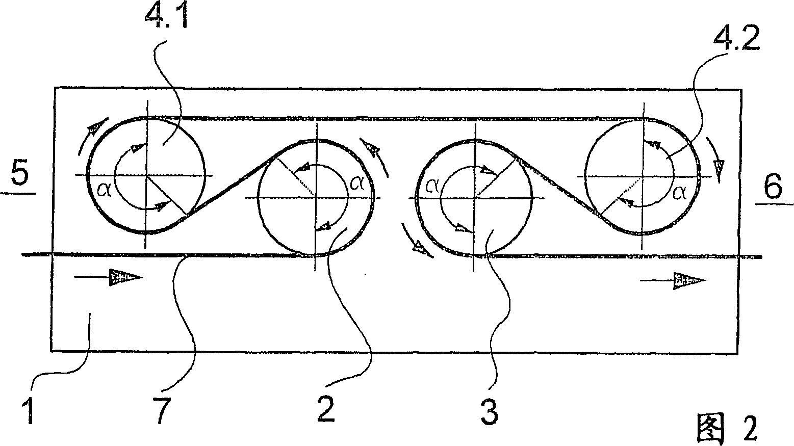
[0027] 1 and 2 schematically show a first embodiment of the device according to the invention. FIG. 1 shows a top view of this embodiment without a guided fiber cable, and FIG. 2 shows a side view of this embodiment with a guided fiber cable. The following description applies to both figures unless it is clearly indicated which figure.

[0028] The input roller 2 , the output roller 3 and the rollers 4 . 1 and 4 . 2 are arranged side by side on the support wall 1 . The rollers 2, 3, 4.1 and 4.2 are of identical construction and are held rotatably on the support wall 1 with a drive end. The rollers 2 , 3 , 4.1 and 4.2 are each coupled with their drive ends to a drive motor 8 . Each drive motor 8 is associated with an inverter 9 by which the drive motor 8 can be controlled.

[0029] The arrangement of the feed roller 2 , the discharge roller 3 and the rollers 4 . 1 and 4 . 2 is selected in such a way that the rollers 4 . 1 and 4 . 2 are held on the support wall 1 at a large d...


PUM


Abstract

Disclosed is a device for guiding, conveying, or treating a fiber cable (7), comprising several driven rollers (2, 3, 4.1, 4.2, 4.3, 4.3, 4.4), the fiber cable being guided along the circumference of the rollers so as to partly wrap therearound. The rollers encompass a roller (2) for feeding the fiber cable and a roller (3) for discharging the fiber cable. The remaining rollers (4.1, 4.2, 4.3, 4.4) are disposed relative to the feeding roller and the discharging roller in such a way that the fiber cable can be guided on the rollers at a respective angle of contact of >180 DEG . In order to involve all rollers to the same extent for guiding, conveying, and treating the fiber cable, the feeding roller and the inlet of the fiber cable as well as the discharging roller and the outlet of the fiber cable are arranged relative to each other such that the fiber cable can be guided along the circumference of the feeding roller and the circumference of the discharging roller so as to partly wrap therearound at a respective angle of contact of >180 DEG .

Description

technical field [0001] The invention relates to a device for guiding, transporting or handling fiber ropes according to the preamble of claim 1 . Background technique [0002] In the production of synthetic fibers, it is known to combine individual spun fiber bundles into a fiber rope and to draw it out of a spinning unit using a device comprising a plurality of driven rollers. In order to pull all the fiber strands forming the fiber rope uniformly from the spinneret, the roller must generate sufficient fiber traction. In order to set a certain spinning titer when guiding the fiber rope, there must not be any slippage between the fiber rope and the rollers—especially in the exit region. All rollers can thus be driven at equal peripheral speeds or at differential speeds for stretching. In order to increase the tractive force and to prevent slipping phenomena, the fiber rope must be guided on the rollers with a defined minimum wrapping angle. The sum of all wrap angles on t...

Claims


Application Information

Patent Timeline
Patent Type & Authority Applications(China)
IPC IPC(8): D01D5/16B65H51/08B65H51/12D01D10/04D01H5/22
CPCB65H51/08B65H51/12D01D10/0436D01D5/16D01D10/00B65H51/00
Inventor H·-J·海德尔A·格林
Owner SAURER GMBH & CO KG
Why Eureka
Try Eureka