Elevator apparatus

A technology for elevators and braking devices, which is applied to elevators, transportation and packaging in buildings, etc., can solve the problems of increased hoistway space, difficult maintenance and inspection operations, and increased axial length, so as to reduce installation space and maintain maintenance. Check the effect of easy work

Inactive Publication Date: 2006-10-18
MITSUBISHI ELECTRIC CORP
View PDF3 Cites 3 Cited by
  • Summary
  • Abstract
  • Description
  • Claims
  • Application Information

AI Technical Summary

Problems solved by technology

[0008] In the existing traction machine of an elevator, there is a driving device and a braking device arranged coaxially with the traction machine, and the braking device is located outside the driving device, so the axial length becomes large
In addition, since the traction machine is installed in the lower part of the hoistway, there is a problem that the use of hoistway equipment such as anti-rope pulleys and ropes increases, and the space on the plane of the hoistway increases, so the cost tends to increase.
In addition, when the traction machine is installed on the top of the hoistway, the operator needs to climb on the car to perform maintenance and inspection of the brake device, so the maintenance and inspection work is very difficult. At the same time, measures must be taken to prevent the operator from failing Protective measures against head hitting the ceiling of the hoistway due to the expected lift of the car

Method used


Image

  • Elevator apparatus
  • Elevator apparatus
  • Elevator apparatus

Examples


Embodiment 1

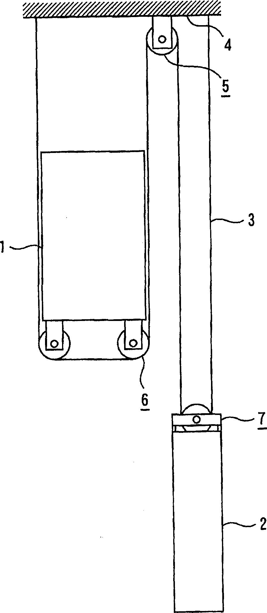
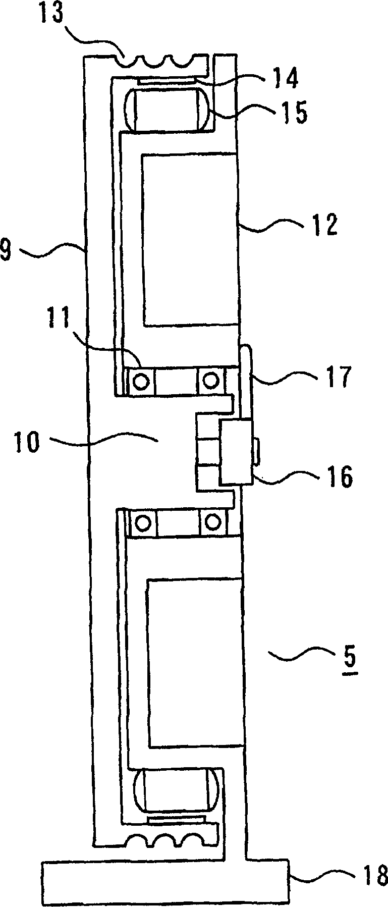
[0027] figure 1 It is a side view showing the overall conceptual structure of the elevator apparatus according to Embodiment 1 of the present invention; figure 2 It is a cross-sectional view showing the structure of the upper anti-sheave of the elevator device according to Embodiment 1 of the present invention, in which the driving device of the traction machine is installed; image 3 It is a cross-sectional view showing the structure of the car-side suspension sheave on which the first braking device of the traction machine is installed in the elevator apparatus according to Embodiment 1 of the present invention; Figure 4 It is a cross-sectional view showing the counterweight side suspension sheave of the second braking device of the traction machine installed in the elevator apparatus according to Embodiment 1 of the present invention; Figure 5 Yes means that there will be installed Figure 4 It is a side view of the state that the suspension wheel on the counterweight ...

Embodiment 2

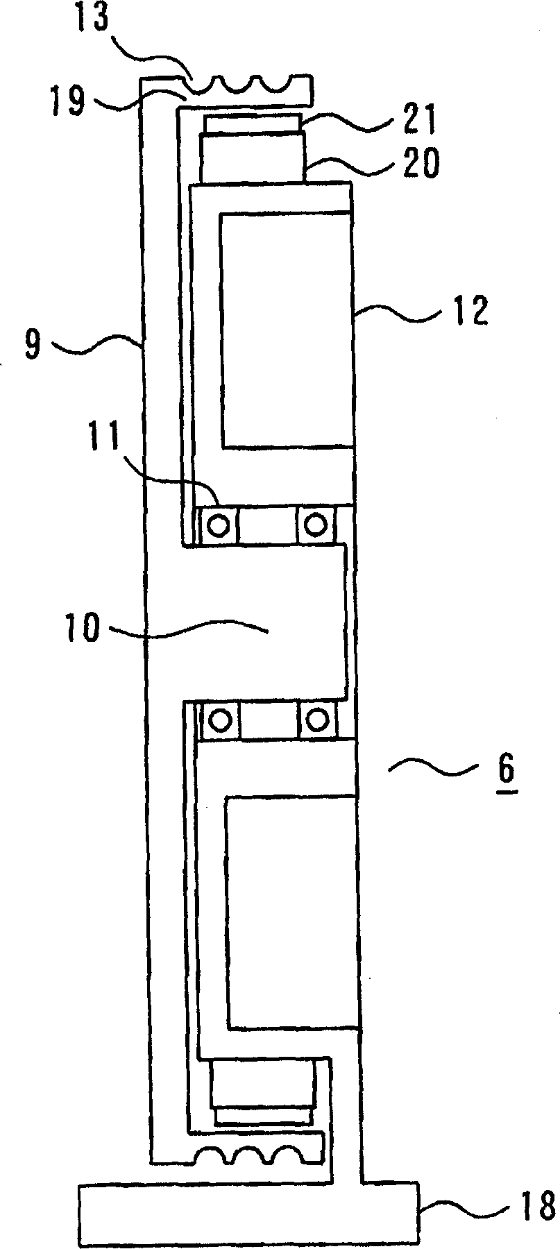
[0037] Figure 6 It is a sectional view showing a car-side suspension sheave to which a first brake device and a second brake device of a hoisting machine are mounted in an elevator apparatus according to Embodiment 2 of the present invention.

[0038] exist Figure 6 Among them, the car side hanging wheel 6 in Embodiment 2 includes: a rotating body 9; a main shaft 10, which is integrally arranged at the central part of the rotating body 9; a base body 12, on which a bearing 11 is pivotally mounted The rotating body 9 and the main shaft 10; the sheave 13, which is arranged on the outer surface of the outer peripheral portion of the rotating body 9, and is wound with the main rope 3; the braking surface 19, which is formed on the inner surface of the outer peripheral portion of the rotating body 9 the first brake 20, which is arranged on the outer periphery of the base body 12; the first brake member 21, which is arranged on the outer side of the first brake 20, and is arrange...


PUM


Abstract

An elevator apparatus enabling the easy maintenance and inspections of a braking device by installing a hoist so that a drive device and a braking device are separated from each other to reduce the installation space for the braking device in a hoistway. The hoist is separated into the drive device and the braking device, and the separated drive device is mounted on an upper return pulley fixed to the top fixed part of the hoistway. The separated braking device is mounted on at least one of car side suspension pulleys and a balance weight side suspension pulley or on both the car side suspension pulleys and the balance weight side suspension pulley.

Description

technical field [0001] The present invention relates to an elevator device, which comprises a traction machine divided into a driving device and a braking device, and the separated driving device and braking device are respectively installed in a hoistway. Background technique [0002] The traction machine of the existing elevator device has a driving device and a braking device together, and the driving device and the braking device are coaxially arranged side by side with the traction machine, and the braking device is arranged outside the driving device (for example, Refer to Patent Document 1). [0003] In addition, there is also an elevator apparatus in which a hoisting machine is installed in a lower portion of a hoistway (for example, refer to Patent Document 2). [0004] In addition, there is an elevator apparatus in which a hoisting machine is installed on the top of a hoistway (for example, refer to Patent Document 3). [0005] Patent Document 1: International Pu...

Claims


Application Information

Patent Timeline
IPC IPC(8): B66B11/08
CPCB66B11/0045
Inventor 中村和且
Owner MITSUBISHI ELECTRIC CORP
Why Eureka
Try Eureka