
Electrically curvable endoscope device

An endoscope and driving device technology, applied to endoscopes, telescopes, medical science and other directions, can solve the problems of no configuration, large-scale structure of the endoscope holding device, etc., and achieve the effect of good operability

Inactive Publication Date: 2006-10-18
OLYMPUS CORP
View PDF3 Cites 8 Cited by
  • Summary
  • Abstract
  • Description
  • Claims
  • Application Information

AI Technical Summary

Problems solved by technology

[0011] However, according to the devices disclosed in the above-mentioned Japanese Patent Application Laid-Open No. 63-122416 and the above-mentioned Japanese Patent Laid-Open No. 2002-224016, there is a problem that the structure of the endoscope holding device is enlarged.
[0012] In addition, the electric bending endoscope devices disclosed in the above-mentioned Japanese Patent Laid-Open No. 7-8442 and the above-mentioned Japanese Patent Laid-Open No. 2002-224016 describe that, for example, the holding part or the control unit of the endoscope holding device is arranged There are various components that make up the bending drive device such as a motor, but there is no description about the specific configuration

Method used


Image

  • Electrically curvable endoscope device
  • Electrically curvable endoscope device
  • Electrically curvable endoscope device

Examples


Embodiment Construction

[0043] Hereinafter, the present invention will be described based on the illustrated embodiments.

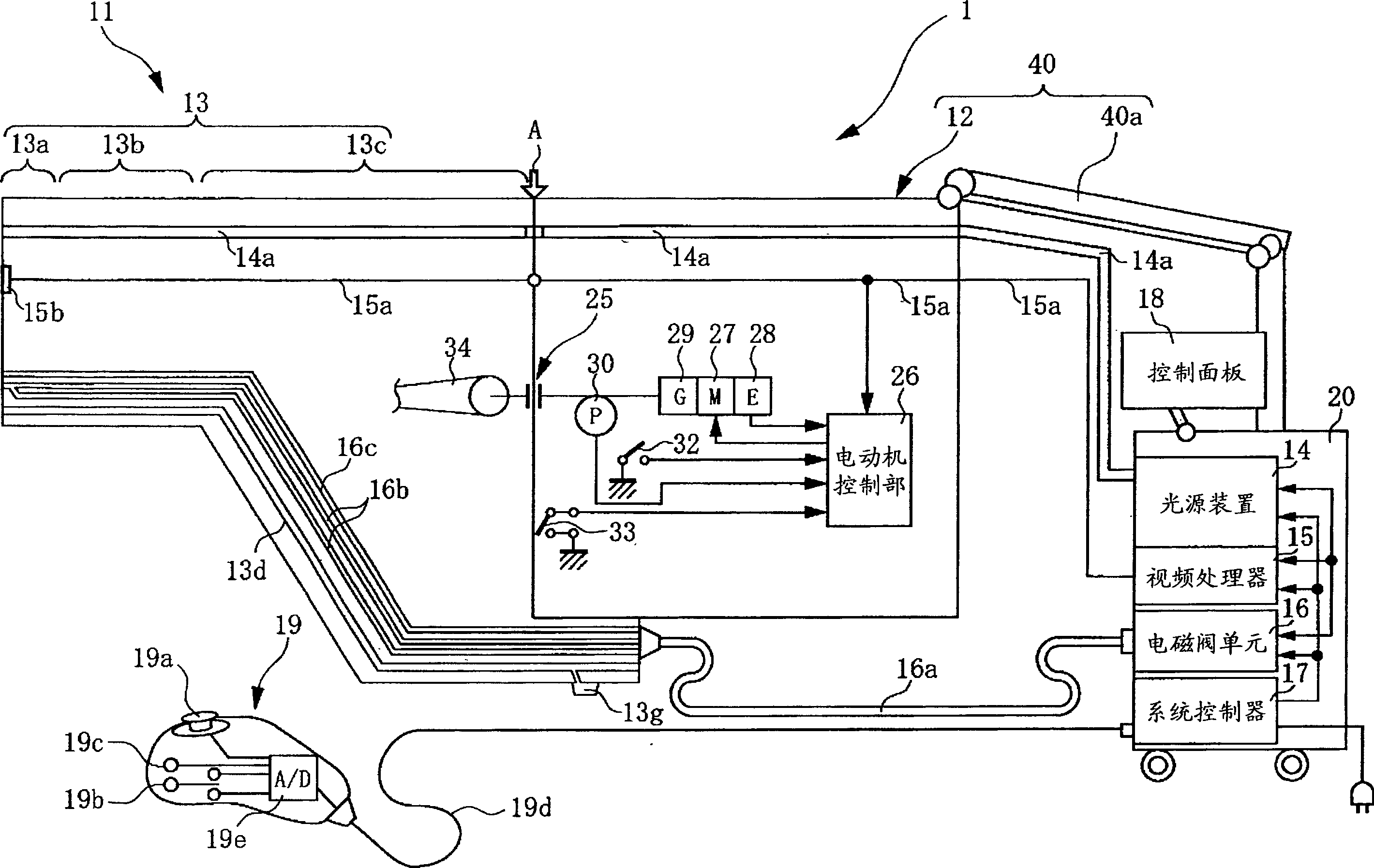
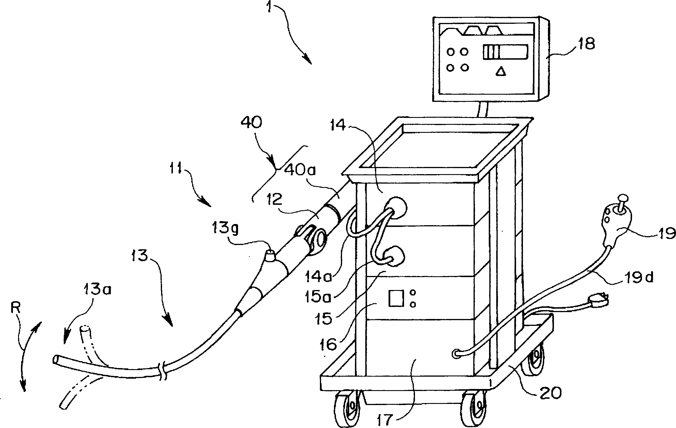
[0044] figure 1 It is a configuration diagram schematically showing the overall configuration of the electric bending endoscope device according to the first embodiment of the present invention. figure 2 It is a perspective view showing the appearance of the electric bending endoscope device according to this embodiment. image 3 It is an enlarged cross-sectional view of main parts showing in detail the connecting portion of the endoscope insertion portion and the holding device in the electric bending endoscope device according to the present embodiment.

[0045] Such as figure 1 As shown, the electric bending endoscope device 1 of this embodiment is mainly composed of the following parts: the electric bending endoscope 11 is an endoscope having the function of observing and treating the body cavity, and is composed of a thin An elongated insertion part 13, an electric bend...


PUM


Abstract

To provide an electric bending endoscope device which can always ensure good operability when using the endoscope without imposing a weight burden on the operator during the operation of the endoscope. The electric bending endoscope device includes at least: an electric bending endoscope capable of observation and treatment in a body cavity, including an elongated insertion portion inserted into the body cavity, and a device for electrically bending and driving a part of the insertion portion. A bending drive device, and an operating part that is separate from the bending drive device and electrically connected to the bending drive device; a system controller, electrically connected to the electric bending endoscope, and controls the electric bending endoscope as a whole; and An endoscope holding device, which includes a bending drive unit with a built-in bending drive device and holds a part of the electric bending endoscope, and an arm connected to and held on the bending drive unit; by attaching and detaching the bending drive unit It is freely connected and arranged on the base end side of the insertion part, and electrically connects the electric bending endoscope and the bending driving device.

Description

technical field [0001] The present invention relates to an electric bending endoscope device, and more particularly to an electric bending endoscope device including an endoscope holding device holding an electric bending endoscope which is electrically curved and driven to be set The bend on the insertion portion of an endoscope. Background technique [0002] Conventionally, the widely used endoscope is configured to observe the organs in the body cavity by inserting the elongated insertion part into the body cavity, or use the treatment instrument inserted in the treatment instrument channel of the insertion part to treat the internal organs as needed. Perform various treatments. [0003] Such a conventional endoscope is generally configured such that a bending portion capable of bending up, down, left, and right is provided on the distal end side of the insertion portion. A bending wire (wire) extending from the operation portion side is connected to the bending portion...

Claims


Application Information

Patent Timeline
Patent Type & Authority Applications(China)
IPC IPC(8): A61B1/00A61B1/04G02B23/24
CPCA61B1/00149A61B1/0052A61B1/0016A61B1/00042
Inventor 池田裕一古川达也小板桥正信上野晴彦金泽宪昭石塚达也正木豊
Owner OLYMPUS CORP
Learn More