
Solar energy enhanced natural ventilating and green lighting system

A technology of natural ventilation and green lighting, applied in the field of building energy saving, can solve problems such as small pressure head, and achieve the effect of reducing building energy consumption, improving ventilation efficiency, and reducing building ventilation and lighting energy consumption

Inactive Publication Date: 2006-10-11
BEIJING UNIV OF TECH
View PDF1 Cites 23 Cited by
  • Summary
  • Abstract
  • Description
  • Claims
  • Application Information

AI Technical Summary

Problems solved by technology

However, the natural ventilation of this system relies on the wind pressure caused by the wind and the heat pressure generated by the temperature difference between indoor and outdoor air to make the air flow, which has the disadvantages of small pressure head and so on.
However, there are no reports on the combination of light pipe green lighting technology and solar chimney enhanced natural ventilation technology.

Method used


Image

  • Solar energy enhanced natural ventilating and green lighting system
  • Solar energy enhanced natural ventilating and green lighting system
  • Solar energy enhanced natural ventilating and green lighting system

Examples


Embodiment approach 1

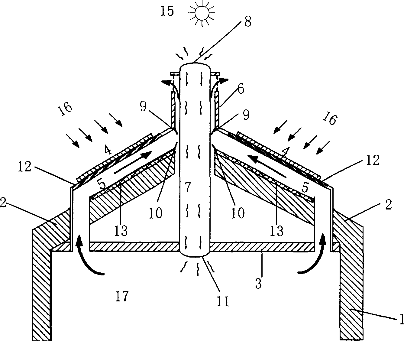
[0030] like figure 1 As shown, the present embodiment is to realize solar energy enhanced natural ventilation and green lighting system for building 1, and this system mainly comprises sloping roof 2, the ceiling 3 that links to each other with sloping roof 2, solar heat collector 4, ventilation channel 5 , heat storage wall 12, heat insulation wall 13, chimney 6, the first valve 9 that controls the air in the ventilation passage 5 to be discharged to the outside, the second valve 10 that controls the air in the ventilation passage 5 to enter the room; wherein, the solar collector The heater 4 is located at the top of the sloping roof 2, the thermal storage wall 12 is located below the solar heat collector 4, the ventilation channel 5 is located between the solar heat collector 4 and the insulating wall 13, and the chimney 6 is located at the top of the sloping roof 2 and is connected with the ventilation exchange. The air passages 5 are connected, and the green lighting light...

Embodiment approach 2

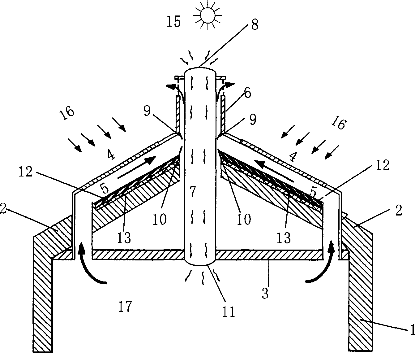
[0034] like figure 2 As shown, the implementation process is similar to that of Scheme 1, except that the thermal storage wall 12 is arranged at the lower part of the ventilation channel 5 and the upper part of the heat insulation layer 13, so as to realize indoor heating in winter, air conditioning in summer and natural ventilation in transitional seasons, and improve the indoor temperature of the building. air quality.

Embodiment approach 3

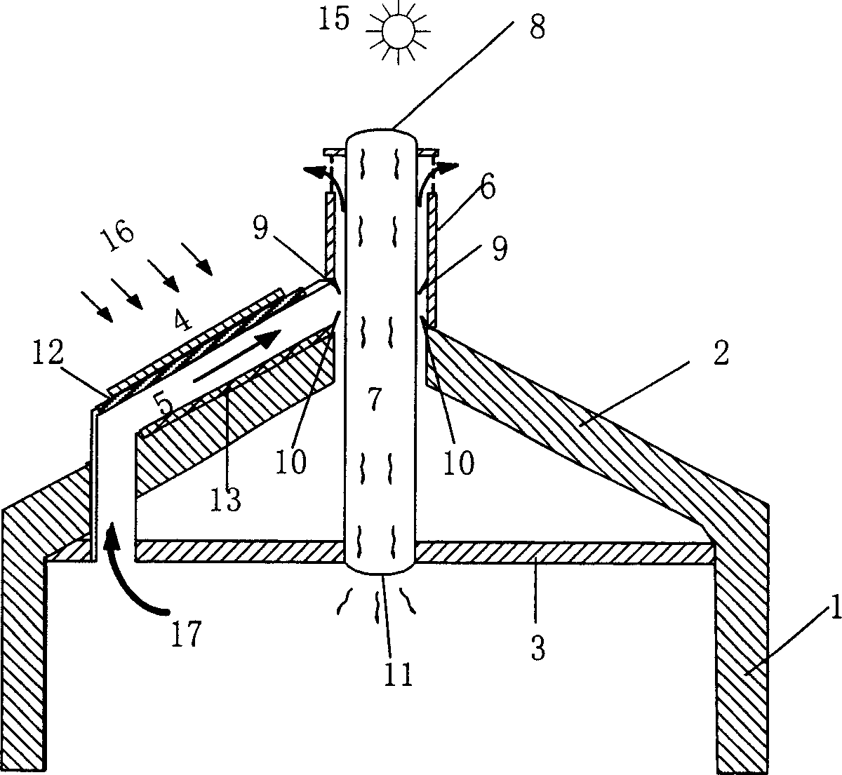
[0036] like image 3 As shown, the implementation process is similar to Scheme 1, except that a set of solar collectors 4 is arranged above the sloping roof 2 to realize indoor heating in winter, air conditioning in summer and natural ventilation in transitional seasons to improve the indoor air quality of the building.


PUM


Abstract

The invention discloses a solar energy strengthened natural ventilate and green lighting system, belonging to the construction energy saving technique. Said invention comprises a light conduction tube system (7), an incline roof (2), a ceiling (3) connected to the incline roof (2), a solar energy collector (4), a ventilating tube (5), a heat accumulating wall (12), a thermal-insulated wall (13), a chimney (6), the first valve (9) and the second valve (10). Wherein, said solar energy collector is at the top of incline roof; the ventilating tube is between the solar energy collector and the thermal-insulate wall; the chimney is at the top of incline roof and connected to the ventilating tube; the central of chimney has an axial green lighting light conductive tube; the inlet of chimney at the end of ventilating tube has the first valve; the end of ventilating tube has the second valve between the thermal-insulated tube and the light conductive tube. The invention can avoid the defects of small ventilating pressure caused by only natural ventilation, to improve the ventilating efficiency.

Description

technical field [0001] The invention relates to a solar energy-enhanced natural ventilation and green lighting system. The system mainly uses the sun's light energy to realize green lighting of buildings, uses the sun's heat energy to strengthen the building's natural ventilation, and simultaneously realizes building heating in winter, air conditioning and transition in summer. Seasonal natural ventilation, to achieve the purpose of building energy saving, belongs to the field of building energy saving. Background technique [0002] my country's building energy consumption is astonishing, and the energy consumed directly and indirectly by building and using buildings accounts for 46.7% of the total energy consumption of the whole society (statistics from the Ministry of Construction). At present, 95% of the existing buildings in our country fail to meet the energy-saving standards, and more than 80% of the newly-added buildings fail to meet the energy-saving standards. envi...

Claims


Application Information

Patent Timeline
IPC IPC(8): F24J2/00F24F7/00
CPCY02B10/20Y02E10/40
Inventor 鹿院卫马重芳吴玉庭王伟
Owner BEIJING UNIV OF TECH
Learn More