
Method and apparatus for realizing uplink outer-loop power control in mobile communication system

A technology of mobile communication system and outer loop power control, which is applied in the direction of transmission control/equalization, etc., and can solve the problem that the transmission power of the transmission channel cannot be adjusted correctly, the transmission power of the mobile terminal is controlled too low or too high, and the receiving signaling signal Improve communication quality and system performance, avoid communication quality degradation, and avoid increased uplink interference

Active Publication Date: 2006-10-04
XFUSION DIGITAL TECH CO LTD
View PDF0 Cites 9 Cited by
  • Summary
  • Abstract
  • Description
  • Claims
  • Application Information

AI Technical Summary

Problems solved by technology

[0013] However, in the above-mentioned existing uplink outer loop power control method, once an abnormality occurs on the IUB interface, the revised target SIR issued by the outer loop power control command to the NodeB will be discarded, which will easily cause the value of the physical channel target SIR to be too high. Low or too high, and because the outer loop power control period may be relatively long, the inner loop power control of the NodeB will control the transmit power of the mobile terminal (UE) too low or too high, and if it is too low, uplink loss of synchronization or call drop will occur Problems, reduce communication quality; too high will lead to increased uplink interference and reduce system performance
[0014] In addition, because the RNC is not comprehensive enough for the outer loop power control in certain business situations, for example, the RNC only corrects the target SIR for a certain transmission channel in the physical channel, resulting in that the transmit power of other transmission channels cannot be adjusted correctly. Reduced communication quality
For example: when the RNC only corrects the target SIR for the traffic channel, if there is a PS service without data transmission, the BLER of the traffic channel is always 0, so the system reduces the transmit power of the UE, which will inevitably lead to the target SIR being too low, resulting in the receiving signal The quality of the signal is reduced, which greatly increases the BLER of the signaling part

Method used


Image

  • Method and apparatus for realizing uplink outer-loop power control in mobile communication system
  • Method and apparatus for realizing uplink outer-loop power control in mobile communication system
  • Method and apparatus for realizing uplink outer-loop power control in mobile communication system

Examples


Embodiment Construction

[0047] The implementation method of the present invention will be further described below with reference to the drawings and specific embodiments.

[0048] According to the 3GPP TS 25.212 protocol, it can be known that the uplink physical channel can be mapped to multiple transmission channels. The present invention is to analyze and compare multiple transmission channels at the same time to perform outer loop power control.

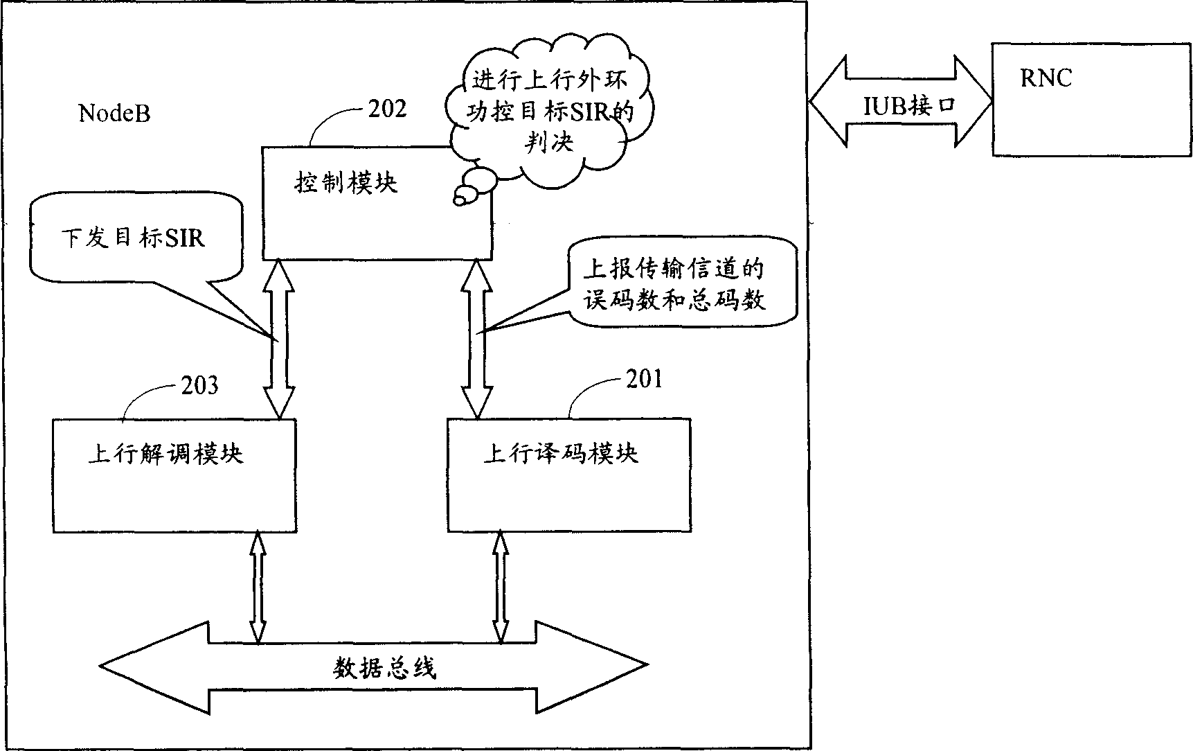
[0049] figure 2 It is the structure diagram of the device for realizing uplink outer loop power control according to the present invention. Such as figure 2 As shown, the outer loop power control of the present invention is performed in the NodeB, and the NodeB assists the RNC to implement uplink outer loop power control. The device is set in NodeB and includes an uplink decoding module 201 and a control module 202, where:

[0050] The uplink decoding module 201 is used to detect the frame data flow in the base station data bus, and report to the control ...


PUM


Abstract

The invention discloses a method and device for achieving upward external ring work control of the moving communicating system. The method stores the object SIR and the corresponding threshold quantity in the base station, which comprises: A. the base station measures the frame quality of each transmitting channel and adjusts the object SIR, and then ascertains the object SIR of the corresponding physics channel; B. it obtains the different value of the object SIR and the wireless net controller (RNC) object SIR; C. it quotes whether the different value is over the threshold quantity, if yes, it makes the object SIR of the base station as upward external ring work control last object SIR; if not, it makes the wireless net controller (RNC) object SI as upward external ring work control last object SIR. The device comprises an upward decoding module and a control module, wherein the upward decoding module is used to detect the frame quality information; the control module dose the external ring work control object SIR quoting by the detected frame quality information.

Description

Technical field [0001] The invention relates to the power control technology of a mobile communication system, and in particular to a method and device for realizing uplink outer loop power control in a wideband code division multiple access (WCDMA) communication system. Background technique [0002] In current wireless communication systems, especially WCDMA systems, power control is one of the key technologies. Power control is abbreviated as power control, and power control can be divided into two categories: inner loop power control and outer loop power control. Among them, the main function of the inner loop power control is to make the received signal-to-interference ratio (SIR, Signal-to-Interference Ratio) converge to the target SIR by controlling the transmit power of the physical channel; the outer loop power control dynamically adjusts the inner loop power control The target SIR ensures that the communication quality always meets the requirements, that is, achieves the...

Claims


Application Information

Patent Timeline
IPC IPC(8): H04B7/005
Inventor 覃勇
Owner XFUSION DIGITAL TECH CO LTD
Learn More