Cable tester
A tester and cable technology, applied in the field of devices for testing various types of cables, can solve problems such as inability to measure long cables, low and inaccurate test accuracy, improve inspection efficiency and accuracy, and reduce a lot of manpower , to ensure the effect of accuracy
- Summary
- Abstract
- Description
- Claims
- Application Information
AI Technical Summary
Problems solved by technology
Method used
Image

Examples
Embodiment 1
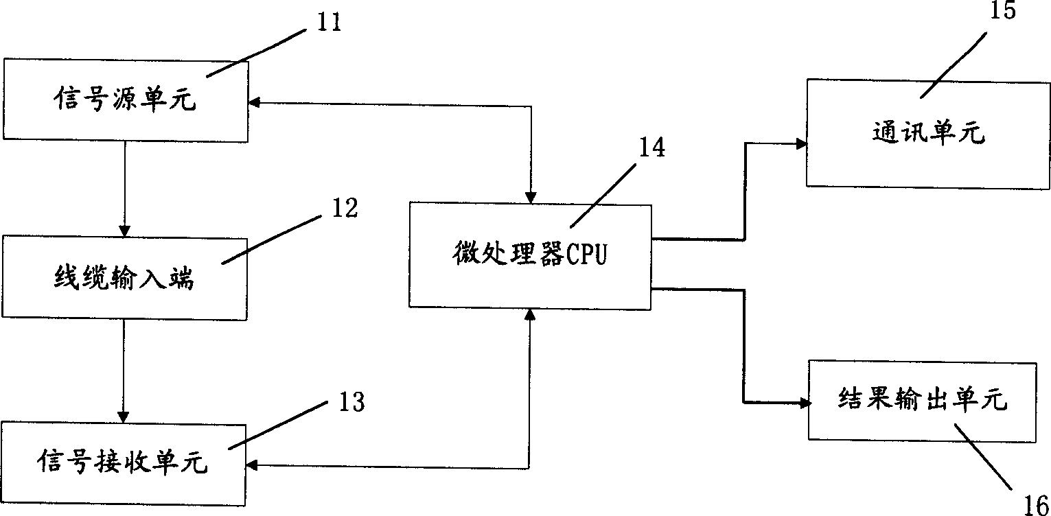
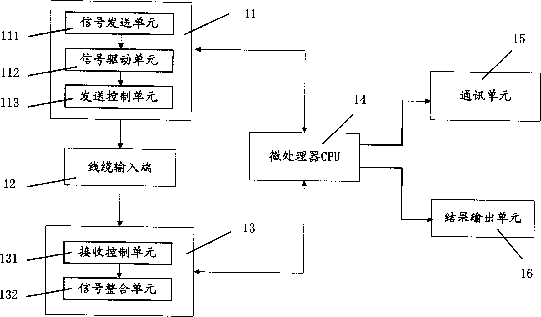
[0042] Example 1, see figure 1 and figure 2 , figure 1 It is a structural schematic diagram of the present invention, figure 2 for figure 1 Schematic diagram of the structure of the first embodiment.
[0043] The cable tester of the present invention includes a signal source unit 11 , a cable input terminal 12 , a signal receiving unit 13 , a microprocessor CPU 14 , a communication unit 15 and / or a result output unit 16 .
[0044] The signal source unit 11 is connected to the microprocessor CPU 14 , and the microprocessor CPU 14 controls the orderly output switching signals, and sends all channel signals to the cable input terminal 12 .
[0045] The signal source unit 11 further includes a signal sending unit 111 , a signal driving unit 112 , and a sending control unit 113 .
[0046] The signal sending unit 111 is controlled by the microprocessor CPU to output a valid switch signal.
[0047] The sending control unit 113 controls the signal sending unit to output a uniq...
Embodiment 2
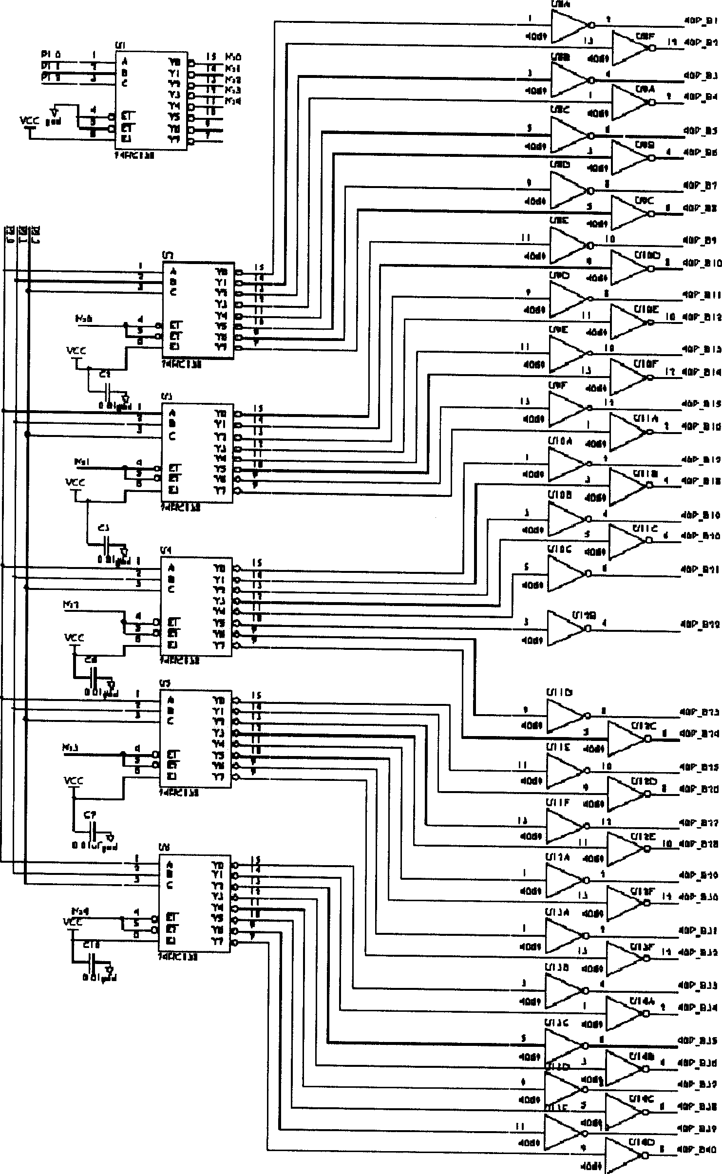
[0063] Example 2, see Figure 3 to Figure 9 It is the specific circuit diagram of the second embodiment. image 3 is the circuit diagram of the signal source unit; Figure 4 is the circuit diagram of the cable input end; Figure 5 is the circuit diagram of the signal receiving unit; Figure 6 is the circuit diagram of the power supply unit; Figure 7 It is the circuit diagram of the microprocessor CPU; Figure 8 is the circuit diagram of the communication unit; Figure 9 Circuit diagram for the result output unit.
[0064] The transmission control unit 113 of the signal source unit 11 of the cable tester in this embodiment may use five 74HC138 decoders. Because the eight-way signal of the decoder 74HC138 itself has the function of only outputting at the same time. Connect the control terminal of a 74HC138 that generates the control signal to the output terminal of another 74HC138, so that only one 74HC138 is selected at the same time. Because only 74HC138 can generate ...
PUM
 Abstract
Description
Claims
Application Information
 - R&D
- Intellectual Property
- Life Sciences
- Materials
- Tech Scout
- Unparalleled Data Quality
- Higher Quality Content
- 60% Fewer Hallucinations
Browse by: Latest US Patents, China's latest patents, Technical Efficacy Thesaurus, Application Domain, Technology Topic, Popular Technical Reports.
© 2025 PatSnap. All rights reserved.Legal|Privacy policy|Modern Slavery Act Transparency Statement|Sitemap|About US| Contact US: help@patsnap.com