
Apparatus and method for monitoring pipeline leakage based on distributed optical fiber acoustic sensing technology

A distributed optical fiber and acoustic sensing technology, used in pipeline systems, gas/liquid distribution and storage, mechanical equipment, etc., can solve problems such as leak location capability and difficulty in detecting leaks

Inactive Publication Date: 2006-09-27
BEIJING UNIV OF TECH
View PDF2 Cites 86 Cited by
  • Summary
  • Abstract
  • Description
  • Claims
  • Application Information

AI Technical Summary

Problems solved by technology

The disadvantage of this technology is: because the distance between the two sensing fibers of this technology is relatively close, the vibration along the pipeline may cause the phase delays of the two sensing fibers to be consistent. At this time, no interference occurs, that is, a reciprocity effect occurs. And when the leak port is away from the direction of the optical cable, it is difficult to detect the leak
The positioning method also has deficiencies. Only when the start time of the pipeline leakage event is captured can the location be located. When the leakage has occurred, this type of detection technology no longer has the ability to locate the leak point.

Method used


Image

  • Apparatus and method for monitoring pipeline leakage based on distributed optical fiber acoustic sensing technology
  • Apparatus and method for monitoring pipeline leakage based on distributed optical fiber acoustic sensing technology
  • Apparatus and method for monitoring pipeline leakage based on distributed optical fiber acoustic sensing technology

Examples


Embodiment Construction

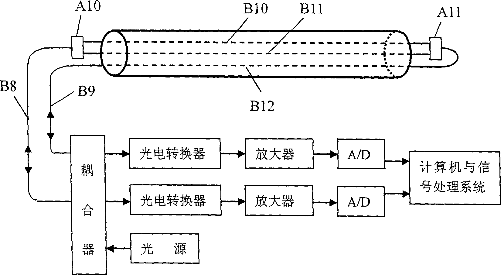
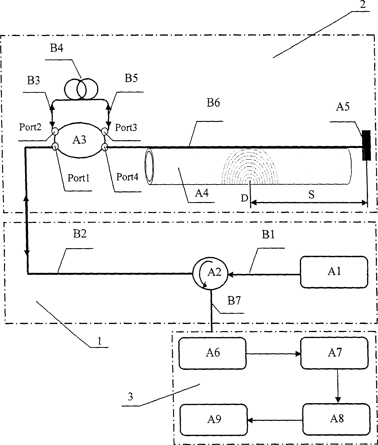
[0029] For the specific structure of this embodiment, see figure 2 , the device is mainly composed of an optical path system 1, a distributed optical fiber sensing system 2, and a detection system 3. Optical path system 1 is composed of JW-3107 ASE broadband continuous light source A1, optical circulator A2, and first guiding fiber B2; distributed optical fiber sensing system 2 is composed of first coupler A3, delay coil B4, and reflector A5; Detection system 3 is composed of 1811 photoelectric converter A6, demodulation system A7, A / D converter A8 and computer A9. Wherein, the ASE broadband continuous light source A1 of the optical path system 1 is connected to the optical circulator A2 through the first single-mode optical fiber B1, and the optical circulator A2 is connected to the Port1 port of the first coupler A3 through the first guiding optical fiber B2, and the first coupling The Port2 port of the coupler A3 is connected to the delay coil B4 through the second single...


PUM


Abstract

The invention relates to a channel leakage detector and method based on distributed optical fiber acoustic sensing technique, which comprises an optical system (1), a distributed optical fiber sensing system (2), and a detecting system (3). Wherein, the optical system comprises a board band continuous light resource A1, and an optical circulator A2; the distributed optical sensing system comprises the first coupler A3, the delay coil B4, and a reflective mirror A5l; the detecting system comprises an optical-electric converter A6, a demodulate system A7, a A / D converter A8, and a computer A9; the board band continuous light resource via the optical circulator is connected to the Port1 interface of the first coupler A3, whose Port2 and Port3 are connected with delay coil; the Port4 of first coupler via sensing optical fiber is connected to the reflective mirror; and the optical circulator is connected to the optical-electric converter of detecting system, while said system can detect any leakage signal at any time.

Description

technical field [0001] The invention relates to a device and a method for monitoring pipeline leakage by adopting interference-type distributed optical fiber acoustic sensing technology, belonging to the field of pipeline leakage monitoring. Background technique [0002] Pipeline is one of the five current means of transportation. It has the advantages of low cost, energy saving, high safety and stable supply in the transportation of liquid, gas and slurry. It is irreplaceable in industries such as petroleum, chemical industry, natural gas and urban water supply. role. With the continuous development of the pipeline transportation industry, in order to maintain the safe operation of the pipeline, the pipeline operation monitoring technology is also constantly developing. [0003] In recent years, with the development of optical fiber sensing technology, long-distance distributed optical fiber sensing technology has also begun to be applied to pipeline leak detection. China...

Claims


Application Information

Patent Timeline
Patent Type & Authority Applications(China)
IPC IPC(8): F17D5/06
Inventor 何存富杭利军吴斌
Owner BEIJING UNIV OF TECH
Learn More