
Single pulse antenna time-space modulating method and device with position and elevation information

A technology of elevation angle information and modulation method, which is applied in the modulation carrier system, phase modulation carrier system, digital transmission system, etc., and can solve the problems that the light wave space modulation method cannot use microwave and microwave space modulation is difficult

Inactive Publication Date: 2006-09-20
NANJING UNIV OF AERONAUTICS & ASTRONAUTICS
View PDF0 Cites 12 Cited by
  • Summary
  • Abstract
  • Description
  • Claims
  • Application Information

AI Technical Summary

Problems solved by technology

In terms of signal modulation, despite the rapid development of radio modulation technology, from single-carrier modulation to OFDM modulation, from time-domain modulation of single-antenna transmission to space-time code modulation of multi-antenna transmission and reception, the main pursuit is to transmit Power efficiency and frequency band utilization are the hotspots of development in the field of communication. It is quite rare to study modulation technology for navigation and positioning and radar detection.
In particular, the modulation technology that organically combines communication and navigation, communication and radar, communication and detection has not yet retrieved relevant information
[0005] At the same time, although the two-dimensional spatial information modulation method for light waves has been widely used, because the transparent electrode for light waves is not transparent for microwaves, the light wave spatial modulation method cannot be used for microwaves, and microwave spatial modulation is still a technical difficulty.

Method used


Image

  • Single pulse antenna time-space modulating method and device with position and elevation information
  • Single pulse antenna time-space modulating method and device with position and elevation information
  • Single pulse antenna time-space modulating method and device with position and elevation information

Examples


Embodiment 1

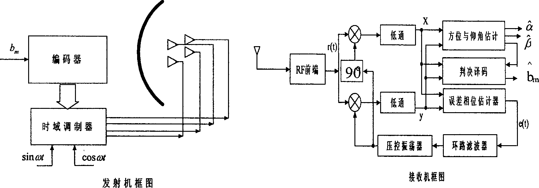
[0044] Such as figure 1 As shown, the monopulse antenna space-time modulation method in which the transmitted signal carries azimuth and elevation angle information in this embodiment uses an amplitude monopulse antenna to transmit signals.

[0045] (1) Design multiple antennas to transmit excitation signals: under the action of four off-focus excitation sources, four concentric off-axis beams are formed, and the beam pattern is F 1 (α,β), F 2 (α,β), F 3 (α,β), F 4 (α, β), abbreviated as F i , i=1, 2, 3, 4, the mutual geometric relationship is as figure 2 As shown, α, β are the directions relative to the central axis of the planar antenna

[0046] Azimuth and elevation angles. The selection of the four beam patterns is the same as that of the monopulse radar, which should have better sum-difference characteristics, but the difference is that all four antennas are used for transmission in this embodiment.

[0047] Let the excitation signal of each antenna beam be s i ...

Embodiment 2

[0078] Embodiment 2: If the information to be transmitted in step (3) of Embodiment 1 is subjected to 16-phase two-bit interval differential encoding, then the differential encoding scheme takes

[0079] ψ(α,β,m)=-ψ(α,β,m-2)+0.5b m πb m The quaternary information is 0, 1, 2, 3, m=1, the initial state of 2 is the same as that of the eight phases, and the azimuth and elevation angle can be measured alternately by odd and even, and the corresponding modulation can be called 16-phase space-time modulation. The communication capacity of the 16-phase time-space modulation is the same as that of the quadrature four-phase QPSK, and the space distance of the encoded signal has nothing to do with the orientation. The simulation results show that the power spectrum of the modulated signal is consistent with QPSK respectively.

Embodiment 3

[0080] Embodiment three: as figure 1 As shown, in the transmitter, the digital information to be transmitted b m It is connected with the encoder, and after encoding, it is output to the time-domain modulator through multiple channels in parallel. The other two inputs of the time-domain modulator are the sine and cosine carriers formed by the frequency synthesizer. The time-domain modulator outputs four channels of modulated signals, which are amplified by radio frequency to excite the antenna, and the space modulation is realized by the reflector antenna to form time-space modulation signals related to azimuth and elevation angles.

[0081] In the receiver, the radio wave signal is first received by a single antenna, and then sent to the radio frequency (RF) front end for amplification and mixing to the intermediate frequency. The intermediate frequency signal is divided into two channels and multiplied by the sine and cosine carrier components output by the local voltage-c...


PUM


Abstract

The method comprises: 1) designing a multiple antenna transmitting drive signal; 2) two dimensional modulation designing is made for said signal; 3) encoding the message to be transmitted; 4) the signal is modulated and transmitted; 5) making carrier extraction and coherent demodulation for the received signal. The invention not only has PSK and QPSK digital communication capacity, but also can make high accuracy direction finding like mono-pulse radar, and is a new architecture of bistatic radar or multistatic radar.

Description

1. Technical field [0001] The invention relates to a modulation method for transmitting signals in a radio system, in particular to a microwave signal space modulation and reception demodulation method with the functions of direction finding and information transmission. 2. Background technology [0002] Transmitting signal design has always been a key issue in radar detection, microwave communication, microwave remote sensing, and radio navigation. However, the design focus of most systems lies in the optimization of the transmitted waveform. There are not many methods that have direction finding function in the transmitted signal. Most direction finding methods do not depend on the form of the transmitted signal. The multi-antenna signal processing algorithm is complex, and it is not easy to miniaturize the receiver. [0003] The method of modulating direction information in the transmitted signal is only used for radio navigation, such as VHF omnidirectional beacons, air...

Claims


Application Information

Patent Timeline
Patent Type & Authority Applications(China)
IPC IPC(8): H04L27/20H04L27/227
Inventor 宋茂忠洪涛杨宇晓
Owner NANJING UNIV OF AERONAUTICS & ASTRONAUTICS
Learn More