
Safety speed reducer for automatic rolling screen window

A technology of invisible screen window and deceleration device, applied in the direction of door/window protection device, window/door, building components, etc., to achieve the effect of improving practicability, safety and simple structure

Inactive Publication Date: 2006-09-13
周世益 +1
View PDF0 Cites 3 Cited by
  • Summary
  • Abstract
  • Description
  • Claims
  • Application Information

AI Technical Summary

Problems solved by technology

[0004] The purpose of this invention is to provide a new type of automatic hidden screen window safety deceleration device, so that the automatic invisible screen window can be rolled back at a uniform speed, so as to solve the common problems of automatic invisible screen window

Method used


Image

  • Safety speed reducer for automatic rolling screen window
  • Safety speed reducer for automatic rolling screen window

Examples


Embodiment Construction

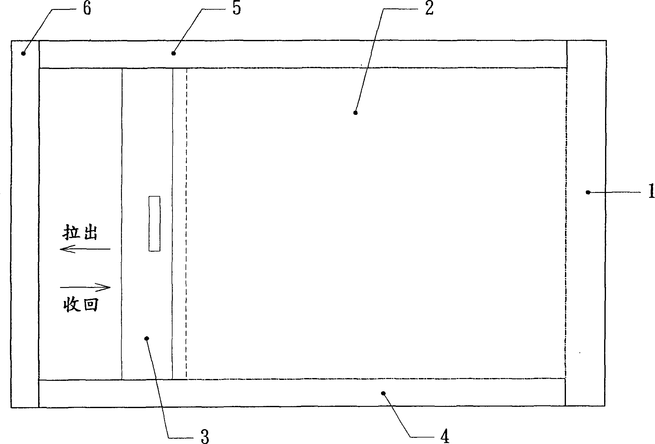
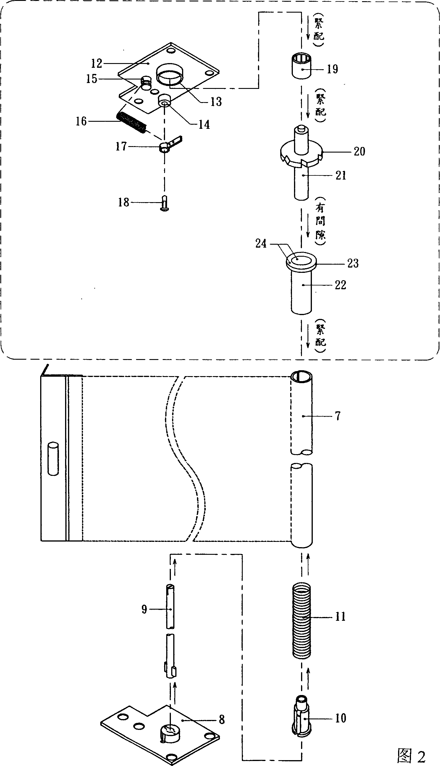
[0011] What Fig. 2 shows is to implement the structural combination of the utility model on an existing automatic invisible screen window.

[0012] A torsion spring (11) is installed in the gauze rolling bar round tube (7). The lower end of the spring (11) is fixedly sleeved on the upper part of the lower plug (10) of the rolling bar round tube. Insert it into the lower plug (10), and there are protrusions on both sides of the lower end to be inserted into the lower plastic plug (8) of the yarn box. The lower plastic plug (8) of the yarn box is a rectangular flat plate (with one corner removed), and Shape is identical with yarn box plastic plug (12).

[0013] The content of the technical solution designed by the present invention is in the upper part of Fig. 2, that is, it is arranged between the yarn box plastic plug (12) and the gauze rolling bar circular pipe (7).

[0014] There is a slight difference between the inner diameter of a section of circular tube-shaped holder (...


PUM


Abstract

The invention relates to a safety reduction gear for an auto-concealed window screen, adding a reduction gear onto the existing auto concealed window screen, where the plastic stopper arranged at the upper end of a screen scroll bar round pipe is a rectangular plate, a lower panel is provided with a segment of round pipe-shaped fixed seat, in which a micro metal one-way bearing is closely arranged in the fixed seat, a round metal bar is closely arranged in inner round hole of the bearing, the middle of lower segment of the round metal bar is provided with a gear-like turnplate, and the lower segment of the round metal bar is inserted in the inner round hole of a round bar sleeve, the upper end of the round bar sleeve is fixed with a sleeve flange disc, and the round bar sleeve is closely arranged in the screen scroll bar round pipe. And it is simple and reasonable in structure, and able to improve practicality and safety of the auto concealed window screen.

Description

technical field [0001] The invention relates to an automatic invisible screen window, in particular to a safety deceleration device for an automatic invisible screen window. Background technique [0002] At present, the automatic invisible screen window adopts a spring rewinding device. After the gauze is pulled out by the tension beam, the torsion spring placed in the gauze box will generate a certain degree of rewinding force, and the automatic invisible screen window relies on the gauze box. The rewinding force generated by the spring will rewind the gauze into the gauze box for storage when the gauze is not in use. Due to the strong rewinding force generated by the spring, the tension beam at one end of the gauze will always be in contact with the gauze box when the gauze is put away. The yarn outlet of the casing collides quickly, causing the gauze to be impacted. In addition to long-term use, it will cause damage to the gauze, the tension beam and the gauze box, becaus...

Claims


Application Information

Patent Timeline
Patent Type & Authority Applications(China)
IPC IPC(8): E06B9/80
Inventor 周世益
Owner 周世益
Learn More