
Radio communication system, radio communication device, radio communication method, and computer program

A technology of a wireless communication system and a wireless communication device, which is applied in the fields of wireless communication systems, wireless communication devices, wireless communication and computer programs, and can solve problems such as inability to permanently confirm, communication quality degradation, etc.

Inactive Publication Date: 2006-09-06
SONY CORP
View PDF1 Cites 3 Cited by
  • Summary
  • Abstract
  • Description
  • Claims
  • Application Information

AI Technical Summary

Problems solved by technology

[0027] Moreover, in the case where the beacon transmission channel of one station is a channel that cannot be used in another station due to an interference channel or a decrease in communication quality, even if these communication stations can communicate with each other on another channel, these communication stations fall into a state of being unable to communicate with each other. A deadlock state in which each other's existence is permanently confirmed

Method used


Image

  • Radio communication system, radio communication device, radio communication method, and computer program
  • Radio communication system, radio communication device, radio communication method, and computer program
  • Radio communication system, radio communication device, radio communication method, and computer program

Examples


no. 1 example

[0269] With the multi-channel communication system according to the first embodiment of the present invention, the level information of the interference received by the local station is described and transmitted in the beacon signal periodically transmitted by each communication station, and based on the signal received from the peripheral station After understanding the interference situation based on the tag information, determine the communication channel. Therefore, the communication channel is controlled in an autonomous decentralized manner by avoiding that a channel which provides interference badly to the outlying stations is used as a communication channel.

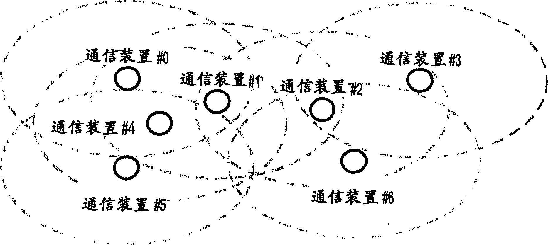
[0270] Now, assume a situation where two or more communication stations are arranged in an interference environment, as shown in FIG. 17 .

[0271] With the wireless communication system shown in the figure, the three channels of channel #1 to channel #3 are prepared as usable channels, but the left and right in ...

no. 2 example

[0365] With the second embodiment of the present invention, each communication station selects a channel with the best communication quality for the local station as the beacon transmission channel, but on the other hand, when transmitting data, each communication station uses a channel with good communication quality. Data transmission is performed on a channel of quality suitable for reception at a communication station serving as a data transmission destination regardless of a beacon transmission channel of the local station.

[0366] Which channel communication quality is suitable for each communication station is easily determined by which channel its communication station uses to perform beacon transmission. Each communication station determines the beacon transmission channel only according to the interference situation of the local station, and this is well known to the general public as the channel for receiving the traffic of the local station, which is convenient for...


PUM


Abstract

PROBLEM TO BE SOLVED: To provide a technology whereby each communication station efficiently makes a frequency allocation in an autonomous distribution multichannel wireless network. ŽSOLUTION: Each communication station transmits a beacon on an optimum channel to its own reception so as not to overlap with beacons of other stations. A communication station obtaining a preferential transmission right after transmission of the beacon shifts to an optimum channel of a receiver side and starts transmission. The communication station shifts to a beacon transmission schedule channel for reception of the beacon when a beacon transmission timing of the other station comes close during a preferential transmission period TGP. When a channel used at present by its own station differs from a channel used by the TGP of the other stations, the channel can be utilized succeedingly even after the reception of beacon. Ž

Description

technical field [0001] The present invention relates to a wireless communication system, a wireless communication device, and a wireless communication method, and a computer program for performing mutual communication between a plurality of wireless stations, such as a wireless LAN (Local Area Network) or a PAN (Personal Area Network), and more particularly Said, relates to a wireless communication system, a wireless communication device and a wireless communication method, and a computer program for establishing a wireless network by autonomous decentralized operation of each communication station without a specific relationship between a controlling station and a controlled station. [0002] More specifically, the present invention relates to a wireless communication system, a wireless communication device and a wireless communication method, and a computer program for forming an autonomous decentralized wireless network without intervention of a specific control station in a...

Claims


Application Information

Patent Timeline
Patent Type & Authority Applications(China)
IPC IPC(8): H04L12/28H04W72/02H04W84/18
Inventor 森冈裕一
Owner SONY CORP
Learn More