Video information device and module unit
A technology of video information and modular units, which is applied in the direction of digital output to display equipment, instruments, and electrical digital data processing, etc., can solve problems such as inability to realize functions, and achieve the effect of realizing development costs
- Summary
- Abstract
- Description
- Claims
- Application Information
AI Technical Summary
Problems solved by technology
Method used
Image


Examples
Embodiment approach 1
[0081]
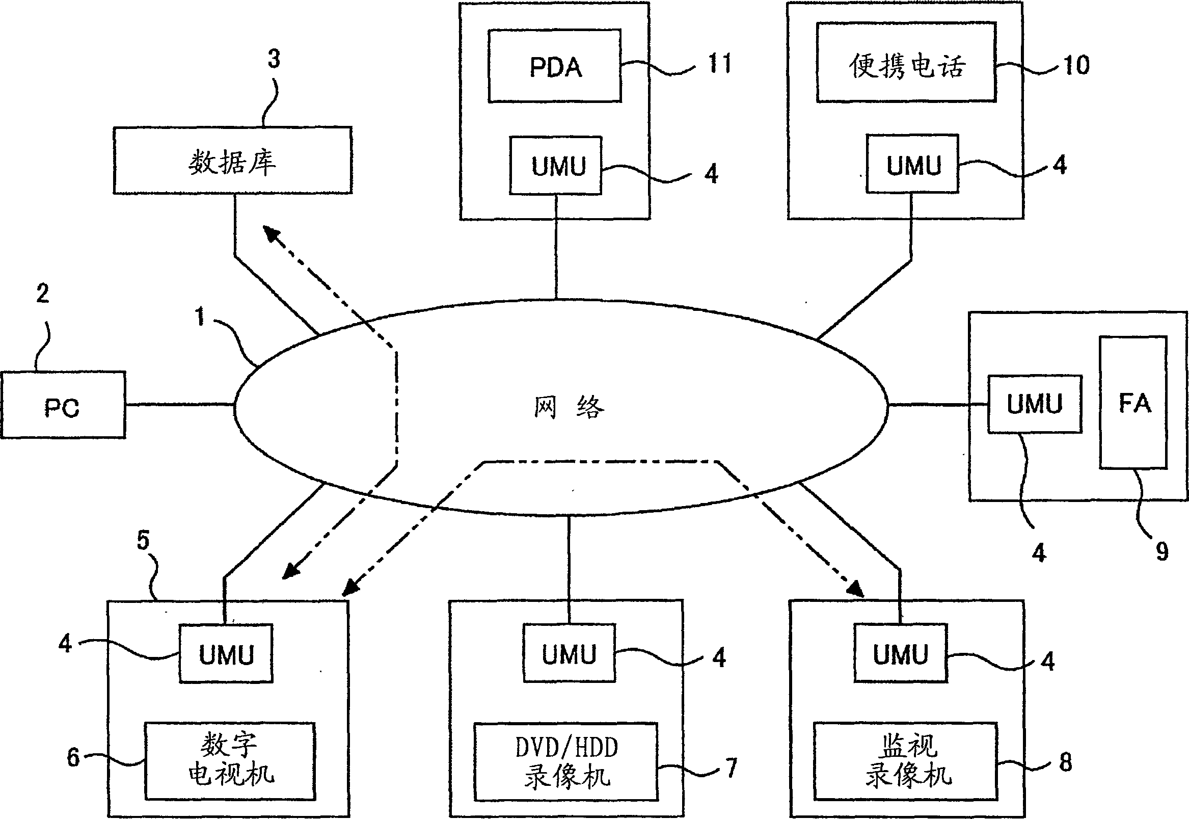
[0082] figure 1 It is a network system diagram including video information devices in Embodiment 1 of the present invention. in addition, figure 1 Various videos such as digital television (digital TV), DVD / HDD video recorder, surveillance video recorder, FA (Factory Automation) equipment in the factory, mobile phone, PDA (Personal Digital Assistant, personal digital assistant) etc. The information devices are respectively connected to the Internet via the module units.
[0083] The network 1 is a network represented by a small-scale LAN, a large-scale Internet, and the like. Generally, unillustrated client computers (client computers) are connected to these networks, and servers (servers) that perform service provision and data transfer to each client computer are connected.
[0084] Also, a computer (here, a personal computer is referred to as a PC) PC2 is a personal computer connected to the network 1, and is used for various services or uses such as sending a...
Embodiment approach 2
[0253]
[0254] Figure 28 It shows a system configuration example in the case where the ubiquitous video module 12 is connected to the Ethernet interface of the video information device 40 .
[0255] The ubiquitous video module unit 4 including the ubiquitous video module 12 has an Ethernet interface 32 f , and the Ethernet interface 32 f is connected to the Ethernet interface 31 e of the video information device 40 .
[0256] Through the connection of the ubiquitous video module unit 4, the video information device 40 communicates / controls with other devices such as network cameras 34d, 34e, and 34f on the LAN 33 via a network such as LAN.
[0257] Here, although the video information device 40 is equipped with a protocol used for communication and control with NAS, it is not equipped with a protocol for communication and control with a network camera outside the device. In such a case, by connecting the ubiquitous video module unit 12, the video information device 40 can...
Embodiment approach 3
[0290]
[0291] FIG. 38 is a diagram showing a system configuration example when the ubiquitous video module unit 4 is connected to the video information device 40 .
[0292] The video information device 40 shown in FIG. 38 is configured to have the S-I / F 31 instead of the drive 55 and the host interface 56 shown in FIG. 7 .
[0293] Furthermore, the ubiquitous video module unit 4 is composed of the ubiquitous video module 12 and the U-I / F 32 . By connecting these respective interfaces S-I / F 31 and U-I / F 32, the video information device 40 having the function of the ubiquitous video module 12 can be realized without developing a new system LSI.
[0294] The ubiquitous video module unit 4 downloads video / audio data and the like from other video information devices on the Internet after being connected to the Internet environment via the communication engine 24 .
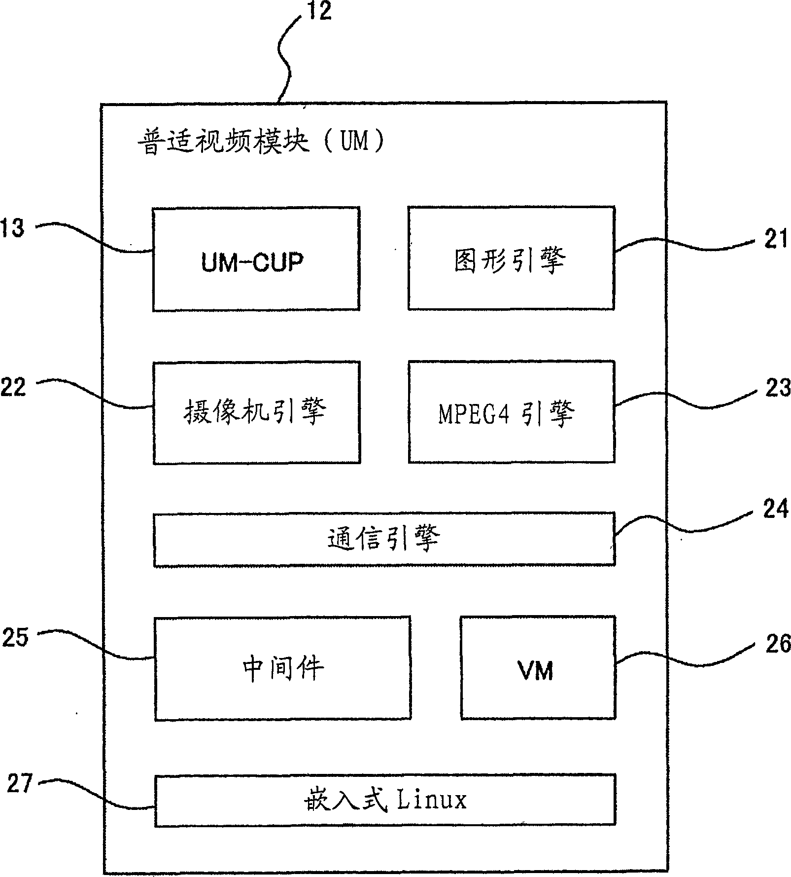
[0295] The MPEG4 engine 23 and the graphics engine 21 included in the ubiquitous video module 12 perform decodin...
PUM
 Abstract
Description
Claims
Application Information
 - R&D
- Intellectual Property
- Life Sciences
- Materials
- Tech Scout
- Unparalleled Data Quality
- Higher Quality Content
- 60% Fewer Hallucinations
Browse by: Latest US Patents, China's latest patents, Technical Efficacy Thesaurus, Application Domain, Technology Topic, Popular Technical Reports.
© 2025 PatSnap. All rights reserved.Legal|Privacy policy|Modern Slavery Act Transparency Statement|Sitemap|About US| Contact US: help@patsnap.com