Thin film transistor and manufacturing method thereof
A technology of thin-film transistors and manufacturing methods, which is applied in the direction of transistors, semiconductor/solid-state device manufacturing, electrical components, etc., and can solve problems such as light leakage
- Summary
- Abstract
- Description
- Claims
- Application Information
AI Technical Summary
Problems solved by technology
Method used
Image

Examples
Embodiment 1
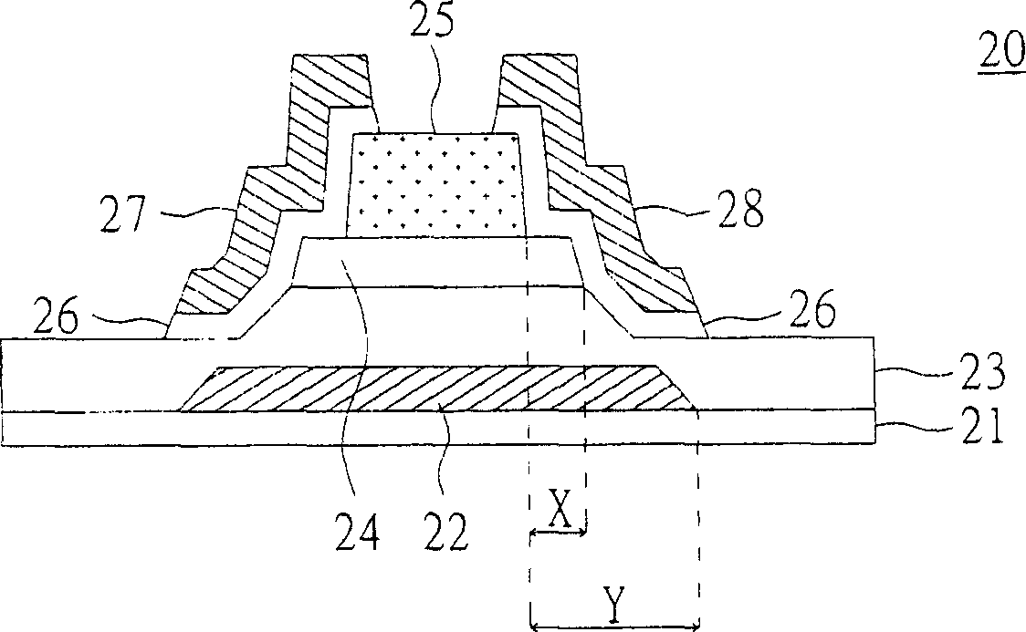
[0059] Please refer to figure 2 , which is a cross-sectional view showing the structure of the thin film transistor according to Embodiment 1 of the present invention. exist figure 2 Among them, the thin film transistor 20 includes a gate 22 , an insulating layer 23 , a channel layer 24 , an etch stop layer 25 , an ohmic contact layer 26 , a source 27 and a drain 28 . The gate 22 is disposed on a substrate 21 . The insulating layer 23 is disposed on the substrate 21 and covers the gate 22 . The channel layer 24 is disposed on a part of the insulating layer 23 and corresponds to the gate 22 , and the width of the channel layer 24 is less than or equal to the width of the gate 22 . The etch stop layer 25 is disposed on a portion of the channel layer 24 and corresponds to the gate 22 , and the width of the etch stop layer 25 is smaller than that of the channel layer 24 . The ohmic contact layer 26 is disposed on a portion of the insulating layer 23 and covers two ends of th...
Embodiment 2
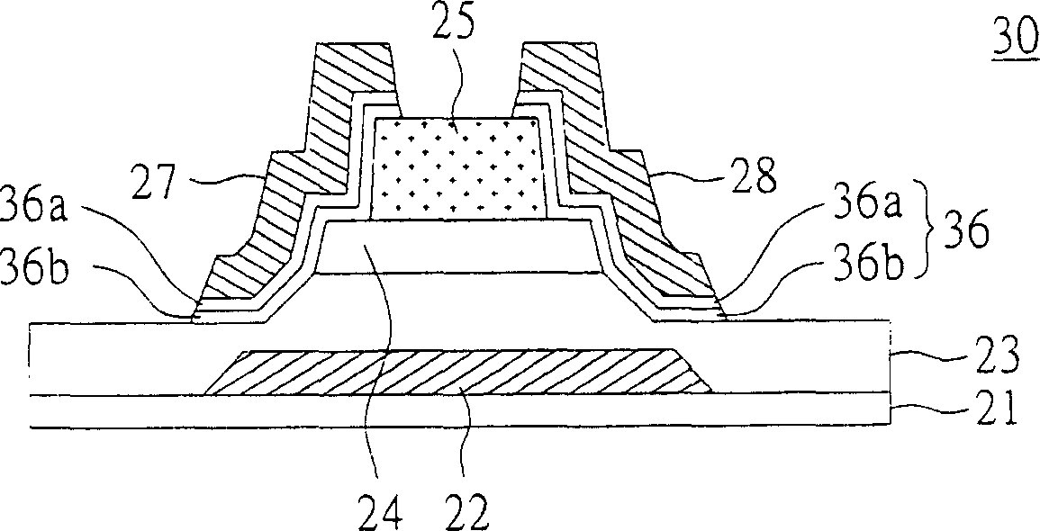
[0064] Please refer to image 3 , which is a cross-sectional view showing the structure of the thin film transistor according to the second embodiment of the present invention. The difference between the thin film transistor 30 of the present embodiment and the thin film transistor 20 of the first embodiment lies in the ohmic contact layer 36 , and the remaining same constituent elements continue to use reference numerals, and the connection relationship between them will not be repeated.
[0065] exist image 3 Among them, the ohmic contact layer 36 includes a first sub-ohmic contact (first sub-ohmic contact) layer 36a and a second sub-ohmic contact (second sub-ohmic contact) layer 36b, and the second sub-ohmic contact layer 36b covers the etch stop layer 25, two ends of the channel layer 24 and part of the insulating layer 23. The first ohmic contact layer 36a covers the second ohmic contact layer 36b, and the source 27 and the drain 28 cover the first ohmic contact layer ...
Embodiment 3
[0068] Please also refer to Figure 4~5L , Figure 4 A flowchart showing a method for manufacturing a thin film transistor according to Embodiment 3 of the present invention, Figure 5A-5L Shown is a process cross-sectional view of a thin film transistor according to Embodiment 3 of the present invention. Please also refer to Figure 2~3 ,exist Figure 4 In step 41, a gate 22 is formed on a substrate 21 first. Such as Figure 5A As shown, the gate 22 covers part of the substrate 21, and the gate 22 includes metal, metal alloy or a combination thereof, and may be a single-layer or multi-layer structure. The substrate 21 includes an insulating substrate, a glass substrate, a ceramic substrate, a plastic substrate or a flexible substrate.
[0069] Next, enter step 42 , form an insulating layer 23 on the substrate 21 and cover the gate 22 . As shown in FIG. 5B , the insulating layer 23 covers the gate 22 and part of the substrate 21 , and the insulating layer 23 includes si...
PUM
 Abstract
Description
Claims
Application Information
 - R&D
- Intellectual Property
- Life Sciences
- Materials
- Tech Scout
- Unparalleled Data Quality
- Higher Quality Content
- 60% Fewer Hallucinations
Browse by: Latest US Patents, China's latest patents, Technical Efficacy Thesaurus, Application Domain, Technology Topic, Popular Technical Reports.
© 2025 PatSnap. All rights reserved.Legal|Privacy policy|Modern Slavery Act Transparency Statement|Sitemap|About US| Contact US: help@patsnap.com