
Method and apparatus for manufacturing vehicle parts

A technology for vehicle parts and components, applied in the direction of household components, transportation and packaging, applications, etc., can solve the problem of difficult placement of inserts, fixing elements and reinforcing elements, etc., to achieve the effect of improving flow characteristics

Inactive Publication Date: 2006-08-16
ECIM TECH
View PDF0 Cites 3 Cited by
  • Summary
  • Abstract
  • Description
  • Claims
  • Application Information

AI Technical Summary

Problems solved by technology

However, this requires specialized injection molding machines and corresponding peripheral equipment, thus making it difficult to place inserts such as labels and the like, fixing elements and reinforcing elements

Method used


Image

  • Method and apparatus for manufacturing vehicle parts
  • Method and apparatus for manufacturing vehicle parts
  • Method and apparatus for manufacturing vehicle parts

Examples


Embodiment Construction

[0025] In the description made, identical or identical components have identical or identical reference numerals.

[0026] The exemplary embodiments shown in the drawings are shown for purposes of illustration only and are not to be considered as limiting in any way.

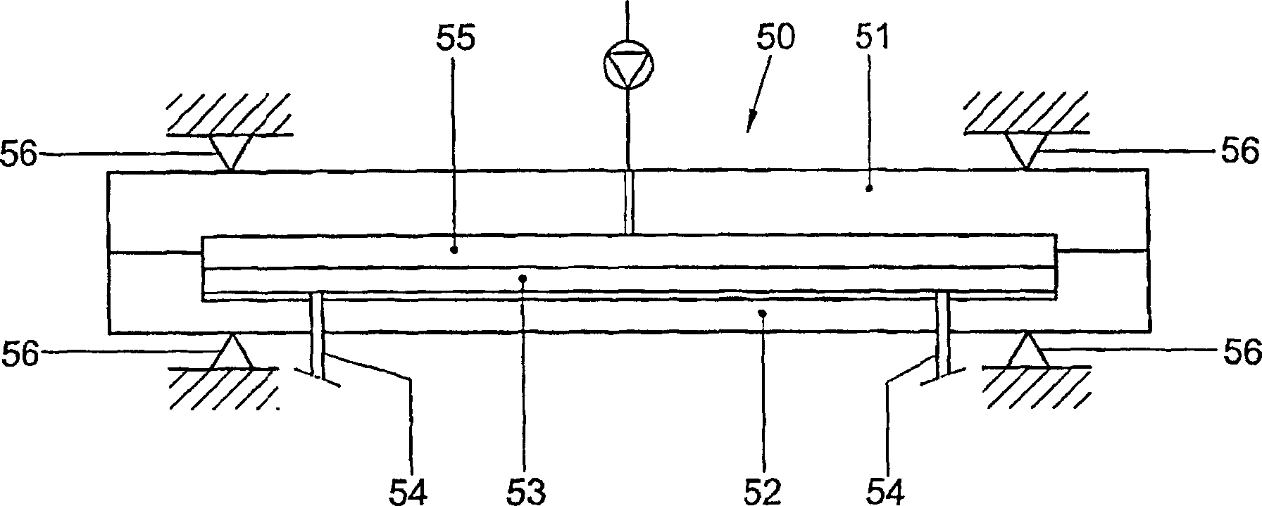
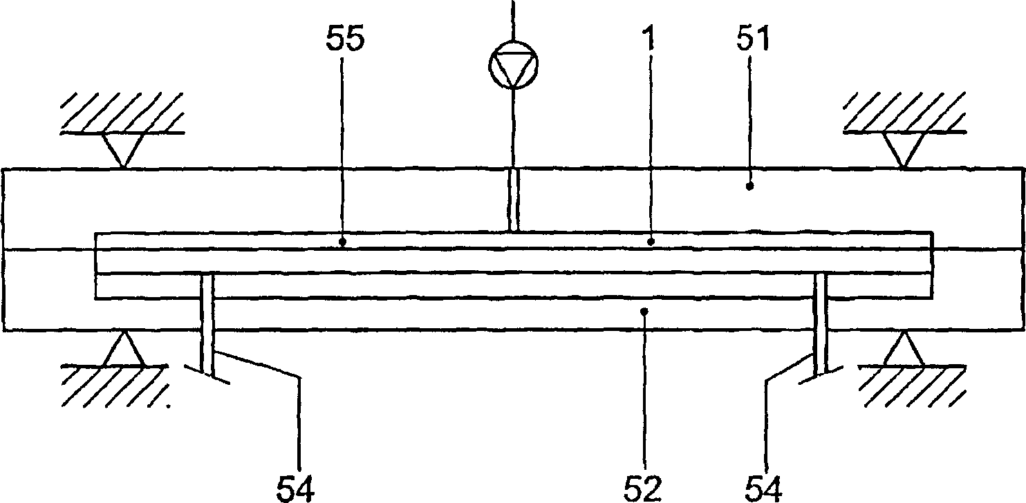
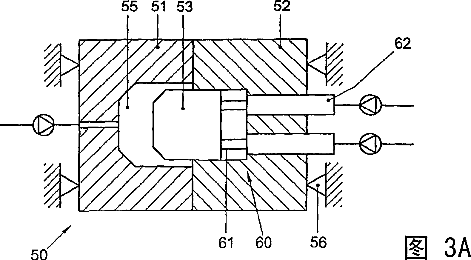
[0027] exist figure 1 In, a mold 50 is shown, which comprises a first part 51 and a second part 52, and in the second part 52 is provided a movable wall element 53 which can pass through figure 1 and 2 The arm 54 shown schematically in FIG. 2 is operated from the outside of the mold 50 . In the mold 50 , the recess forms a cavity 55 , a part of which is delimited by a movable wall element 53 . In the cavity 55 , a vehicle component 1 , for example a cover element, can be formed. When starting the injection molding operation, the movable wall element 53 is retracted in the first position, in other words, the space of the cavity 55 is relatively large and the plastic is introduced into the cavity 55 . Subsequ...


PUM


Abstract

The invention relates to a method for manufacturing at least partly plastic vehicle parts in a mold with at least one mold cavity, comprising the steps of: at least partly closing the mold, wherein the at least one mold cavity is brought in a first position by means of at least one movable wall part of the at least one mold cavity; introducing plastic into the at least one mold cavity; upon complete closure of the mold and / or movement of the at least one movable wall part, bringing the at least one mold cavity in a second position, the at least one mold cavity in the second position having a different volume than in the first position; all this in such a manner that by bringing the at least one mold cavity from the first into the second position, the plastic fills the respective mold cavity completely.

Description

technical field [0001] The invention relates to a method for producing vehicle components from plastic in a mold. Background technique [0002] Plastic vehicle parts are usually manufactured by injection molding. Since these parts are usually relatively large in proportion to their wall thickness, very large heavy-duty injection molding machines are required, which are expensive to purchase and operate. The increase of wall thickness can make the flow easier, but it will prolong the injection molding cycle, and it will also increase the use of materials, increase the weight, and cause adverse stress. So this is a less than ideal workaround. [0003] It has previously been proposed to use cascade injection molding techniques, in which case a flow front moving through the mould is obtained. However, this requires specialized injection molding machines and corresponding peripheral equipment, thus making it difficult to place inserts such as labels and the like, fixing elemen...

Claims


Application Information

Patent Timeline
Patent Type & Authority Applications(China)
IPC IPC(8): D04H1/00B29C45/56B29C45/14B29C45/16
CPCB29L2031/3041B29C45/14311B29C2045/563Y10T428/249921B29C45/14778B29K2713/00Y10T428/31504B29C2045/0098B29L2031/3005Y10T442/3854Y10T442/30B29C2045/564Y10T442/20B29C45/561Y10T442/3049B29C45/1635B29C45/14B29C45/56D04H1/00B29C45/16
Inventor 亨德里克斯·安东尼厄斯·霍格兰
Owner ECIM TECH
Learn More