Exposure apparatus

An exposure device and mask technology, which is applied in photolithography exposure devices, microlithography exposure equipment, optics, etc., can solve the problems of large errors, time-consuming, difficult to apply, etc.

Inactive Publication Date: 2006-08-16
ORC MFG
View PDF3 Cites 3 Cited by
  • Summary
  • Abstract
  • Description
  • Claims
  • Application Information

AI Technical Summary

Problems solved by technology

[0009] However, in the technique described in Patent Document 1, the alignment of the entire substrate is performed first, alignment is performed on any divided area in an appropriate order, and exposure is performed from the area where the alignment has been completed. Therefore, after dividing into four areas, In the case of , the calibration of the entire substrate requires five calibration steps, and even in the case of dividing into two areas, it is necessary to perform three calibration steps, which is time-consuming
[0010] Moreover, since the entire substrate is calibrated first by using the mask and the marks on the substrate, the error becomes larger after the calibration is performed on each area.
[0011] Since the technology described in Patent Document 2 is a method of measuring the center of gravity position of each pattern to be exposed and the center of gravity position of the whole, based on the measured data, correcting the reference position information of each of the plurality of regions, and based on the corrected data, , to expose each pattern, therefore, the exposure of each pattern takes time, and it is difficult to apply it to a device such as an exposure device for a printed circuit board that directly exposes the pattern of the mask by making the mask and the substrate close middle

Method used


Image

  • Exposure apparatus
  • Exposure apparatus
  • Exposure apparatus

Examples


Embodiment Construction

[0023] Hereinafter, embodiments of the exposure method of the exposure apparatus according to the present invention will be described with reference to the drawings.

[0024] The present invention is an exposure apparatus that calibrates a substrate having a plurality of calibration marks for positioning, and a mask having mask marks for aligning positions with the calibration marks and a mask provided with a predetermined pattern. Exposure is carried out in a state where it fits on the substrate.

[0025] First, the exposure device will be described.

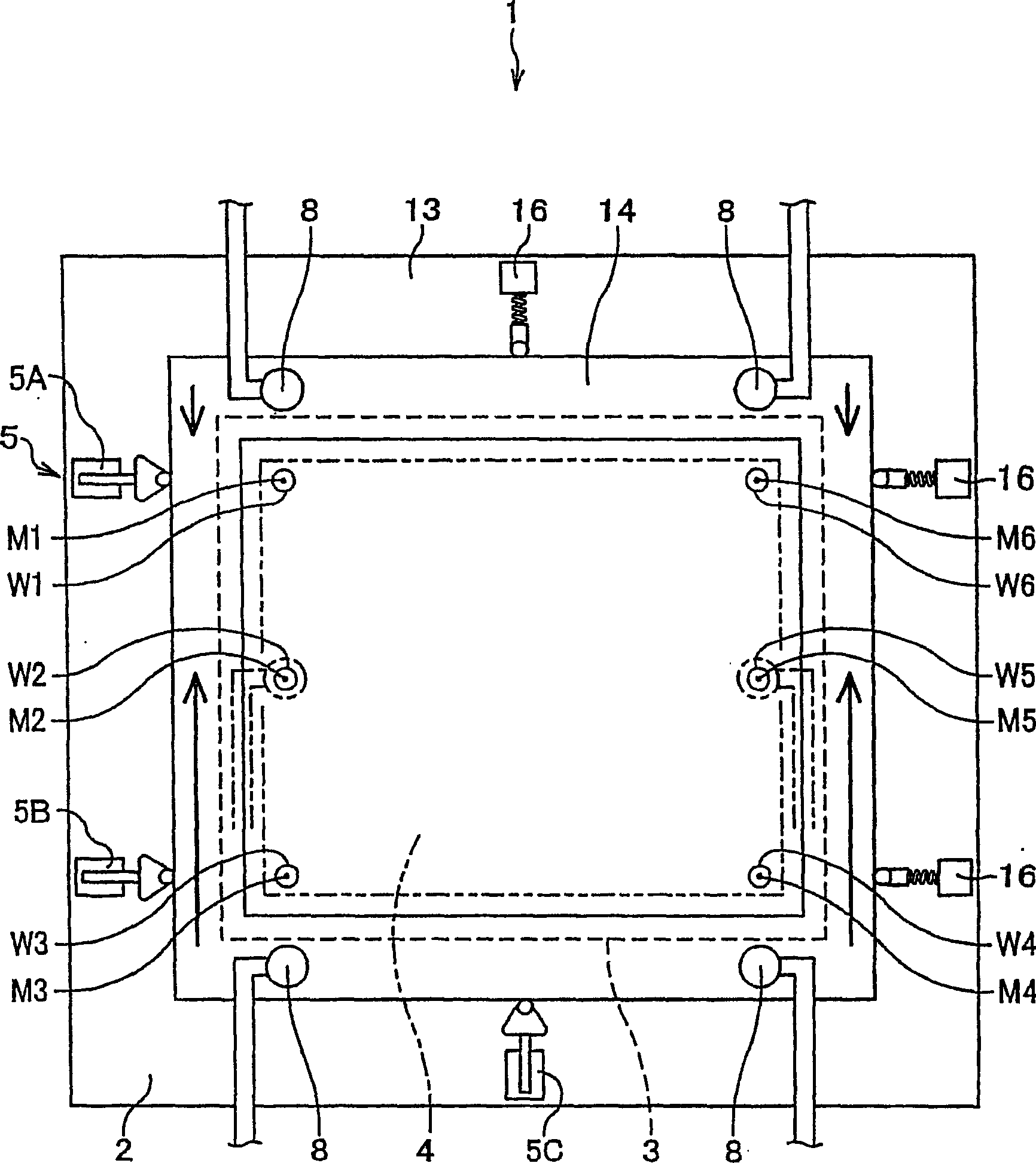
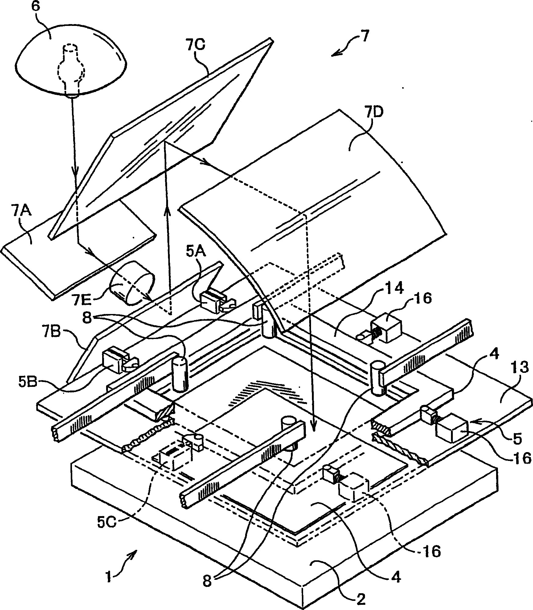
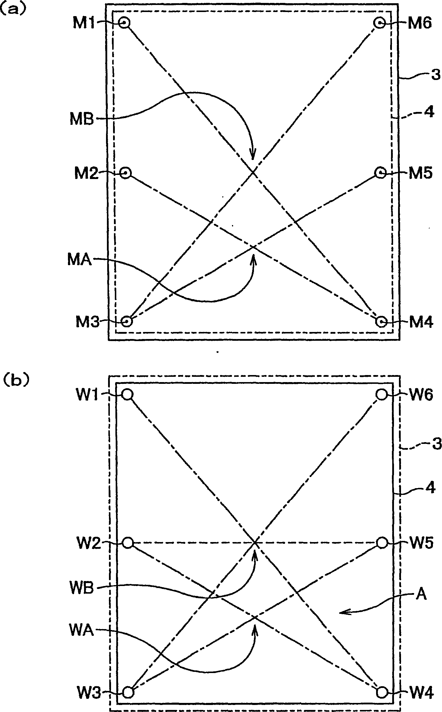
[0026] In the attached drawings, figure 1 It is a plan view showing main parts of the exposure apparatus. figure 2 It is a three-dimensional schematic diagram of the whole exposure device. image 3 (a) is a schematic diagram showing the arrangement of mask marks on the mask. image 3 (b) is a schematic diagram showing the arrangement of alignment marks on the substrate. Figure 4 A schematic side view of the exposure devic...


PUM


Abstract

An exposure apparatus is used for calibrating a substrate and a photomask and carrying out exposure in a state of sealing the photomask in the substrate, wherein the substrate includes a plurality of calibration marks for location; and the photomask includes a plurality of photomask marks for aligning to the calibration marks and is provided with a prescribed pattern. The exposure device comprises a unit for calculating distribution point MB obtained by crossing diagonals of the entire region of the photomask on the basis of the plurality of photomask marks; a unit for calculating distribution point WB obtained by crossing diagonals of the entire region of the substrate on the basis of the calibration marks; a first comparison unit for comparing the distribution point MB of the photomask marks with the distribution point WB of the calibration marks; and a first determination unit determining whether the distribution point WB of the calibration marks lie in an allowable range with respect to the distribution point MB of the photomask marks according to the comparison result of the first comparison result, wherein an exposure beam is irradiated on the entire substrate when the first determination unit determines that the distribution points WB lie in the allowable range.

Description

[0001] This application is based on Article 42 of the Implementing Regulations of the Patent Law of the People's Republic of China. It is a divisional application of the invention patent application with the title of "Exposure Method for Exposure Device" and application number 200410048823.8 submitted on June 4, 2004. technical field [0002] The invention relates to an exposure device for substrates such as printed circuit boards and liquid crystal substrates and masks, in particular to an exposure device for performing exposure operations according to distribution points (points) between masks and substrates. Background technique [0003] Patent Document 1: Japanese Unexamined Patent Publication No. 11-194507 (paragraphs 0011-0014, image 3 ) [0004] Patent Document 2: Japanese Unexamined Patent Publication No. 2000-122303 (full text) [0005] Conventionally, when producing a printed circuit board, an exposure device is used which aligns a mask provided with a circuit pat...

Claims


Application Information

Patent Timeline
Patent Type & Authority Applications(China)
IPC IPC(8): G03F7/20G03F9/00H05K3/00H01L21/027
Inventor 屋木康彦薮慎太郎氏益稔
Owner ORC MFG
Why Eureka
Try Eureka