Generations of sequences of waveforms

一种波形、序列的技术,应用在生成波形序列领域,能够解决不能够增加峰值自相关值等问题

Inactive Publication Date: 2006-08-09
MITSUBISHI ELECTRIC CORP
View PDF3 Cites 7 Cited by
  • Summary
  • Abstract
  • Description
  • Claims
  • Application Information

AI Technical Summary

Problems solved by technology

[0021] Although the method disclosed in the prior application provides a practical solution to the problem of reducing mutual interference effects in a multi-user environment, the method cannot increase the peak autocorrelation value R xx (0) = the ratio R of N to the maximum (unit) autocorrelation sidelobe value

Method used


Image

  • Generations of sequences of waveforms
  • Generations of sequences of waveforms
  • Generations of sequences of waveforms

Examples


Embodiment Construction

[0061] Description of preferred embodiments

[0062] The system structure according to the present invention will be described below. First, the type of interrogation signal used for such a system is mentioned.

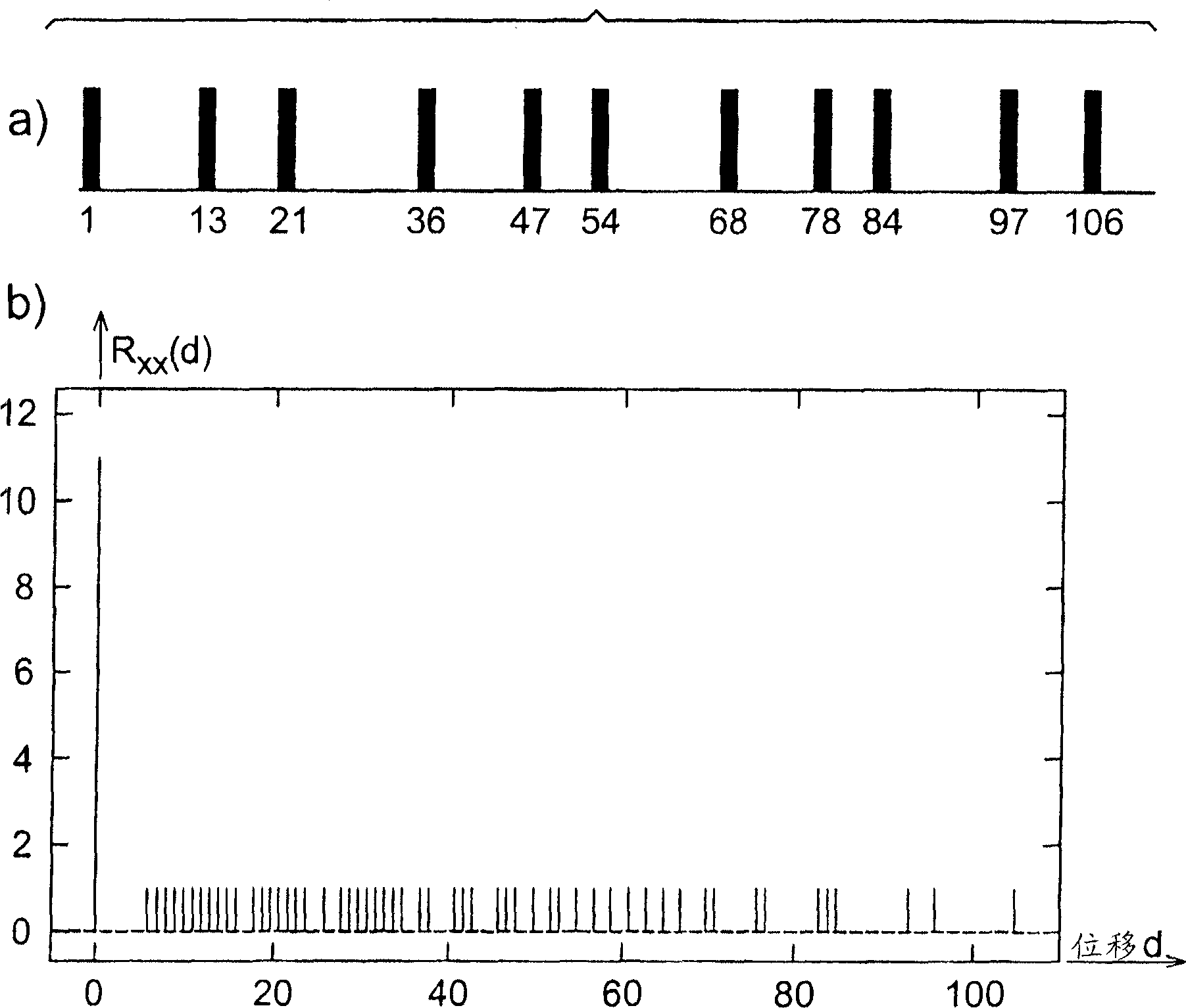
[0063] figure 2 (a) shows an example of a basic pulse set that can be used to derive the interrogation signal used by the obstacle detection system according to the invention. The set consists of 11 pulses distributed over 106 positions; the minimum difference between pulse positions in the set is equal to 6 (positions 78 and 84). figure 2 (b) depicts the autocorrelation sequence of the group. This group satisfies the modified autocorrelation constraints described above. According to the group structure, the zero correlation region has a span of 5.

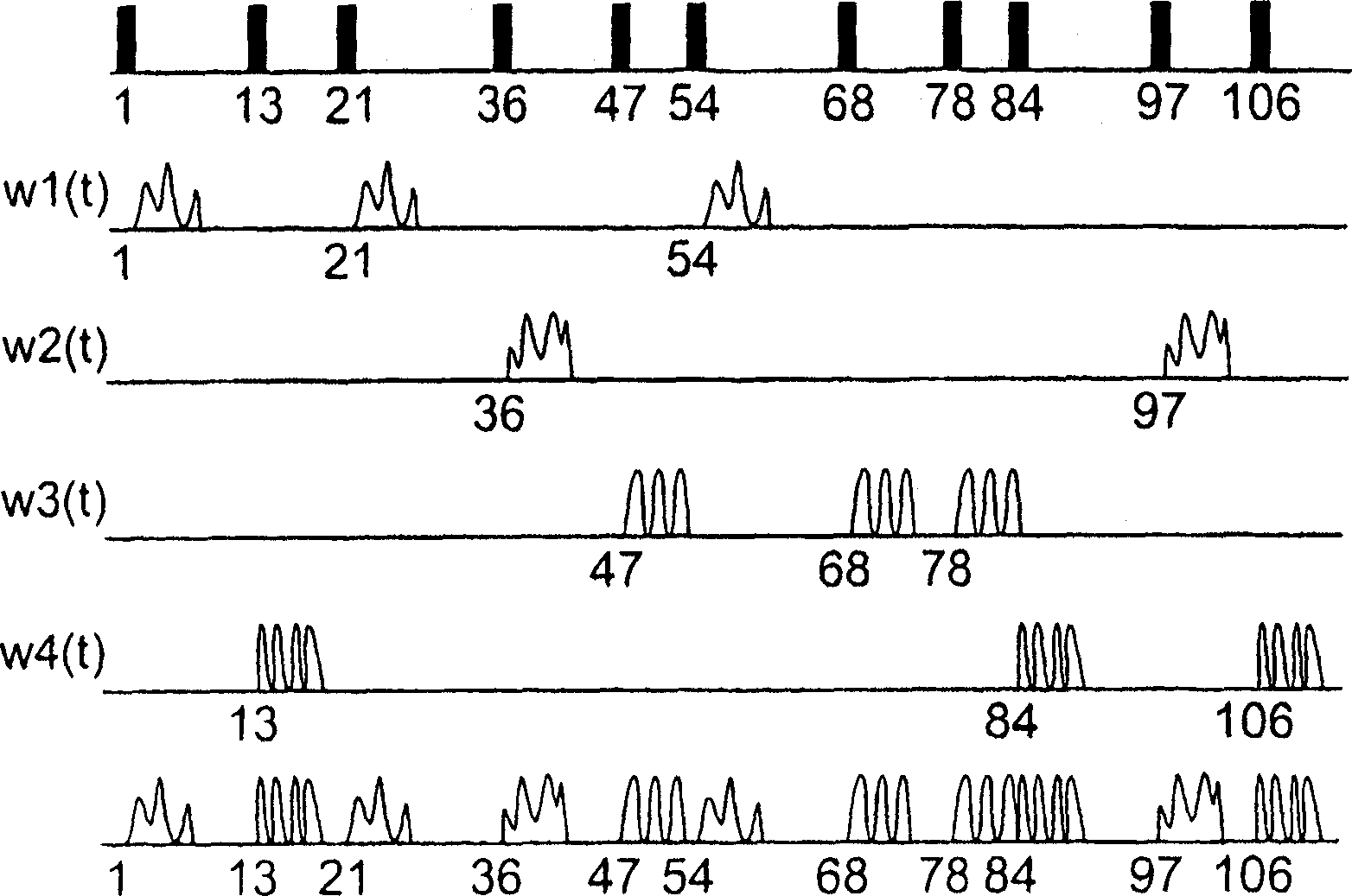
[0064] Randomly selected waveforms can be substituted for individual pulses. In the simplest configuration, the duration of each waveform for random pulse mapping is equal to Δ, the duration of each elementary pul...


PUM


Abstract

The signals within a packet of transient signals are generated at timings corresponding to a binary pulse sequence having an autocorrelation function which, for all non-zero shifts, has a value which is substantially smaller than the maximum value at zero shift. The times of occurrence of the signals within a packet are such that the minimum gap between adjacent pulses in the corresponding binary pulse sequence exceeds a predetermined value, whereby the autocorrelation function of the binary pulse sequence exhibits a zero value for consecutive relative shifts which do not exceed a predetermined limit. Each transient signal may be a randomly-selected waveform with predetermined characteristics. At least one packet may be based on a composite sequence including a first binary pulse sequence interleaved with a second binary pulse sequence which is a time-reversed replica of the first binary pulse sequence, at least a substantial number of the transient signals corresponding to each binary pulse sequence being distinguishable from those corresponding to the other binary pulse sequence.

Description

field of invention [0001] The present invention relates to a method and apparatus for generating a sequence of waveforms, for example in an obstacle detection system, especially but not limited to blind spots or pre-crash ) used in the alarm system. Background of the invention [0002] An important type of automotive blind spot or pre-collision warning system uses short bursts of electromagnetic or ultrasonic energy to interrogate a detection zone. Decisions about the presence or absence of obstacles within a predetermined range are then made by appropriately processing the energy backscattered by different objects within the field of view of the system. The detection device is arranged to detect whether the reflected pulse occurs within a certain delay (corresponding to a predetermined range) after the interrogation pulse has been transmitted. Instead of merely detecting the presence of reflected pulses, the analog value of the signal received after each pulse transmissio...

Claims


Application Information

Patent Timeline
Patent Type & Authority Applications(China)
IPC IPC(8): G01S13/30G01S13/22G01S13/24G01S13/26G01S7/03G01S7/292H03K3/84G01S7/282G01S13/10G01S13/931
CPCG01S13/30G01S13/106G01S7/282G01S13/931G01S2013/9332G01S2013/9315
Inventor W·J·绍诺夫斯基
Owner MITSUBISHI ELECTRIC CORP
Why Eureka
Try Eureka