Spliced heat-conductive floor board

A technology for heat-conducting floors and boards, applied in heating methods, household heating, heating systems, etc., can solve the problems of easy deformation of the floor, difficult to achieve the effect of heat conduction and heat preservation, warping, etc. The effect of not easy to deform and long service life

Inactive Publication Date: 2006-08-09
郭清涛
View PDF0 Cites 5 Cited by
  • Summary
  • Abstract
  • Description
  • Claims
  • Application Information

AI Technical Summary

Problems solved by technology

However, practice has proved that it is difficult to achieve the best heat conduction and heat preservation effect.
And this kind of floor is easily deformed and warped during the heating process

Method used


Image

  • Spliced heat-conductive floor board
  • Spliced heat-conductive floor board
  • Spliced heat-conductive floor board

Examples


Embodiment Construction

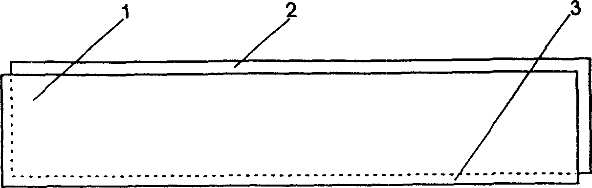
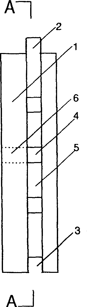
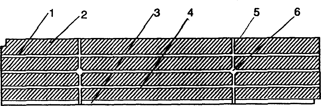
[0018] Example: according to Figure 1 to Figure 5 As for the assembled heat conduction floor of the present invention with the above-mentioned structure, the length of the floor is selected in the range of 300×50~1000×300mm, and the sizes of other components are matched with it according to the ratio shown in the figure. see Figure 1~5 , take a floor blank with a thickness of 14 mm as the board body 1, and planer planer longitudinal groove pipes 4 and transverse groove pipes 5 on the board surface of the board body 1. The number of the longitudinal grooved tubes 4 is more than 3 (including 3), and the number of the transverse grooved tubes 5 is more than 2 (including 2). Then drill 2 perforated hole pipes as guide pipe 6 on the grooved pipe. Then on the four sides of the board body 1, as in the making of traditional assembled floors, the tenon 2 is planed out on the adjacent two sides, and the tenon groove 3 is planed out on the other adjacent two sides. The processed blan...


PUM


Abstract

An improved spliced heat conduction floor has a matrix floor with a tenon and a slot mortise, a longitudinal slot pipe and a horizontal slot pipe are crossly connected in the matrix floor, a gas conduction hole under which is connected with the two pipes, so the ground hot gas under the floor can be conducted into the two pipes via the heat conduction hole to heat the floor quickly.

Description

technical field [0001] The invention relates to an improved assembled floor, in particular to a heat conduction floor suitable for geothermal heating in cold regions. Background technique [0002] With the improvement of people's material living standards, the floors of various buildings and villas also need to be upgraded. And existing geothermal heating floor, great majority still is by adopting sheet material to transfer heat energy. It is also possible to increase the heat conduction function, heat circulation performance and thermal insulation performance of the floor by processing mesh grooves on the back of the board. However, practice has proved that it is difficult to achieve the best heat conduction and heat preservation effects. And this floor is easily deformed and warped during the heating process. Today, almost every household needs to be equipped with a safe, practical, and magnificent heat-conducting floor wherever conditions permit. The project is very la...

Claims


Application Information

Patent Timeline
Patent Type & Authority Applications(China)
IPC IPC(8): E04F15/022F24D3/12
Inventor 郭清涛
Owner 郭清涛
Why Eureka
Try Eureka