Overfiring air port, method for manufacturing air port, boiler, boiler facility, method for operating boiler facility and method for improving boiler facility
A technology of boiler equipment and air port, which is applied in the field of air port for fuel combustion, can solve the problem that the balanced reduction of NOx concentration and CO concentration is not considered, and achieve the effect of reducing NOx concentration and CO concentration
- Summary
- Abstract
- Description
- Claims
- Application Information
AI Technical Summary
Problems solved by technology
Method used
Image
Examples
Embodiment 1-1
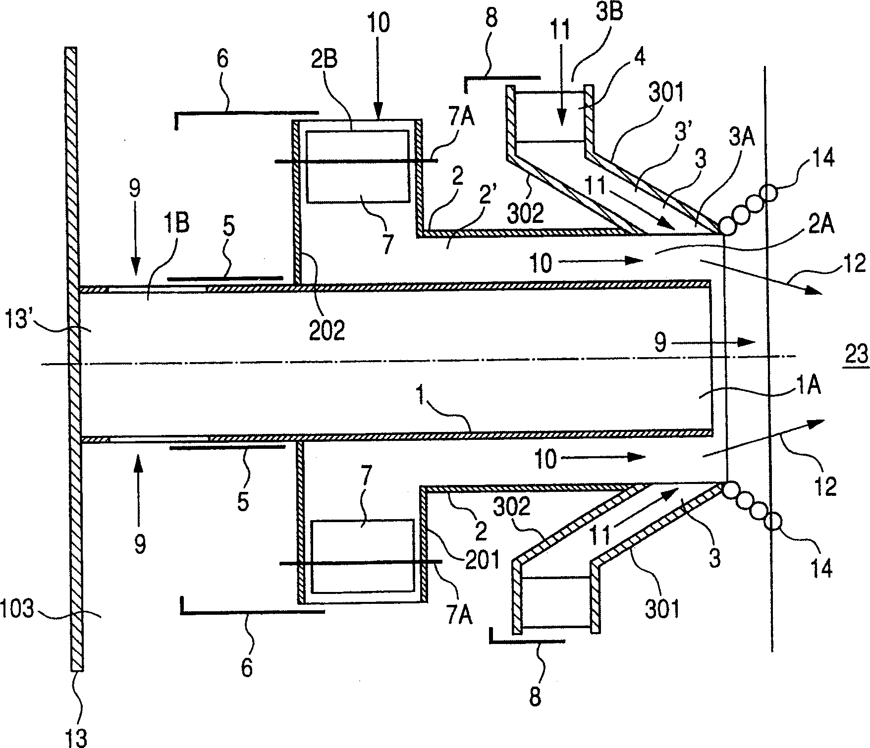
[0089] figure 2 is a cross-sectional view showing Embodiment 1 of the air port of the present invention ( Figure 4 A-A' section view), image 3 is a perspective view with a part omitted, Figure 4 It is a figure which shows the air port seen from inside a furnace. Figure 5 is a graph showing the flow velocity at the outlet of the air port. Figure 6 , 7 8 and 8 are schematic diagrams showing the relationship between the state of air flow in the furnace 23 and the incomplete combustion area (where there are many combustible gases).
[0090] The air port 100 is arranged in the bellows 103 . The air nozzle mechanism of the air port has the primary nozzle 1, the secondary nozzle 2 that ejects the air that swirls along the outer periphery of the primary nozzle as secondary air, and the air that flows from the outer side of the primary nozzle 1 to the center line of the air port. Tertiary nozzle 3 as tertiary air jet.
[0091] The primary nozzle 1, the secondary nozzle 2, a...
Embodiment 1-2
[0113] Fig. 9 is a sectional view showing Embodiment 1-2 of the air port 100 of the present invention.
[0114] The difference from Embodiment 1-1 is that a movable sleeve 15 movable in the axial direction by operating a handle 21 from the outside is provided between the outer periphery of the primary nozzle 1 and the inner periphery of the secondary nozzle 2 . Furthermore, a movable sleeve 16 movable integrally with the movable sleeve 15 is provided. That is, the movable sleeve has a two-layer structure.
[0115] The movable sleeves 15 , 16 are connected to each other by a connecting member 18 and are movable in the axial direction by guide rollers 17 . A movable sleeve 15 is guided and movable in the axial direction on the inner circumference of the secondary nozzle 2 , and on the one hand a movable sleeve 16 is guided and movable on the outer circumference of the primary nozzle 1 .
[0116] Since the movable sleeve 15 becomes a part of the wall of the secondary nozzle 2, ...
Embodiment 1-3
[0125] Fig. 12 is a sectional view showing Embodiment 1-3 of the air port of the present invention.
[0126] Although this example also has movable sleeves (movable nozzle: nozzle adjusting member) 15, 16, it is different from Embodiment 1-2 in the following points. In this example, among the conical front wall 301 and rear wall 302 constituting the tertiary nozzle 3 , the rear wall 302 can slide in the axial direction. The opening area of the outlet 3A of the tertiary nozzle can be changed by sliding the rear wall 302 . In this example, the rear wall 302 is integrated with the movable sleeve 15 of the secondary nozzle 2 , and the rear wall 302 can also move simultaneously when the movable sleeve 15 is moved. The front wall 301 is fixedly supported in the bellows 13 .
[0127] Even in this embodiment, when the flow rate of the tertiary air 11 is reduced (including zero flow rate) and the flow rate of the secondary air is increased, the movable sleeve 15 is moved closer to ...
PUM
 Abstract
Description
Claims
Application Information
 - Generate Ideas
- Intellectual Property
- Life Sciences
- Materials
- Tech Scout
- Unparalleled Data Quality
- Higher Quality Content
- 60% Fewer Hallucinations
Browse by: Latest US Patents, China's latest patents, Technical Efficacy Thesaurus, Application Domain, Technology Topic, Popular Technical Reports.
© 2025 PatSnap. All rights reserved.Legal|Privacy policy|Modern Slavery Act Transparency Statement|Sitemap|About US| Contact US: help@patsnap.com


