
Evaporating device and method utilizing same

A technology of vapor deposition and vapor deposition, which is applied in the direction of gaseous chemical plating, coating, electrical components, etc., can solve the problems of low source gas use efficiency and difficulty in obtaining high-quality insulating films, etc., and achieve excellent characteristics, crystallization or annealing The effect of easy process

Active Publication Date: 2006-07-26
SAMSUNG DISPLAY CO LTD
View PDF0 Cites 13 Cited by
  • Summary
  • Abstract
  • Description
  • Claims
  • Application Information

AI Technical Summary

Problems solved by technology

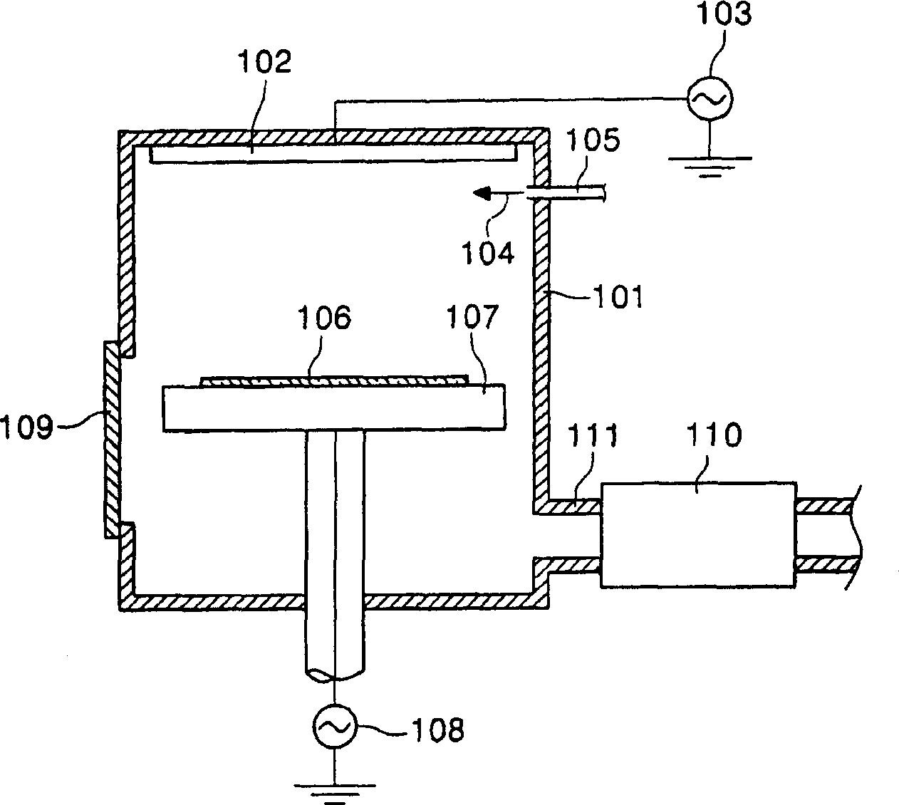
[0008] However, the above chemical vapor phase device cannot completely decompose the source gas because it only utilizes the plasma method to evaporate the insulating film. Get High Quality Insulation Film

Method used


Image

  • Evaporating device and method utilizing same
  • Evaporating device and method utilizing same
  • Evaporating device and method utilizing same

Examples


Embodiment 1

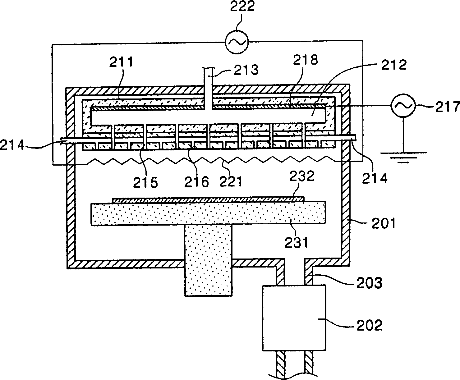
[0053] refer to figure 2 For description, the substrate 232 is placed on a jig of the vapor deposition apparatus of the present invention including a shower head and a heating body.

[0054] Next, use the vacuum pump 202 to exhaust the gas inside the chamber 201 to make the vacuum degree less than or equal to 5×10 -6 torr. The temperature of the wall of the chamber is preferably maintained at a temperature greater than or equal to 120° C., because when the temperature of the chamber is low, the evaporated material is not deposited on the substrate but deposited in the chamber. Problem spot on the wall etc.

[0055] Then, after an inert gas is injected into the first gas injection port 213 , electric power is applied to the electrode 218 to generate plasma inside the cavity 212 . At this time, since the inert gas is a gas for generating plasma, helium (He), neon (Ne), argon (Ar), or the like can be used. At this time, the flow rate of the inert gas is 1-1000 sccm. In addi...

Embodiment 2

[0063] refer to figure 2 For description, the substrate 232 is placed on a jig of the vapor deposition apparatus of the present invention including a shower head and a heating body.

[0064] Next, use the vacuum pump 202 to exhaust the gas inside the chamber 201 to make the vacuum degree less than or equal to 5×10 -6 torr. The temperature of the chamber wall is preferably maintained at a temperature greater than or equal to 120° C., because when the temperature of the chamber is low, there are evaporators that are not deposited on the substrate but deposited in the chamber. Problem spot on the wall etc.

[0065] Then, after an inert gas is injected into the first gas injection port 213 , electric power is applied to the electrode 218 to generate plasma inside the cavity 212 . At this time, since the inert gas is a gas for generating plasma, helium (He), neon (Ne), argon (Ar), or the like can be used. At this time, the flow rate of the inert gas is 1-1000 sccm.

[0066] T...


PUM


Abstract

The invention discloses an evaporation equipment and the method thereof. The evaporation equipment decomposes the gas which requires high energy through plasma decomposition and heating, and decomposes the gas which requires less energy through heating; in this way, an evaporation body is developed on the substrate. When molding an insulating film with a current ICP-CVD device or a PEVCD plasma device, the source gas is difficult to be totally decomposed, which impairs the property of the evaporation body and leads to low service efficiency of the source gas. In the purpose of avoiding the above defects, the invention provides an evaporation equipment with plasma and / or heating working modes and an evaporation method thereof.

Description

technical field [0001] The present invention relates to a vapor deposition method, and more specifically, to a vapor deposition device for forming a vapor deposition on a substrate using a hybrid chemical vapor deposition device using a plasma method or / and a heating body method and using the vapor deposition method. Device vapor deposition method. Background technique [0002] Plasma environments are used in various fields related to thin films, such as chemical vapor deposition, etching, and surface treatment. This is because there is an advantage that the plasma state can improve reaction efficiency in these steps, and the steps can be performed under favorable conditions. [0003] Since plasma formation methods vary depending on the purpose of using plasma, various plasma formation devices are also being developed. Recently, in semiconductor manufacturing processes and the like, plasma processing apparatuses using high-density plasma capable of further improving proces...

Claims


Application Information

Patent Timeline
Patent Type & Authority Applications(China)
IPC IPC(8): C23C16/448C23C16/48C23C16/04C23C16/52C23C16/54C23C16/26C23C16/42
CPCC23C16/45565H01L21/67207C23C16/345F04D17/168C23C16/4412H01L21/0262
Inventor 金汉基许明洙金明洙李奎成郑锡宪
Owner SAMSUNG DISPLAY CO LTD
Learn More