Ultrasonographic device
A diagnostic equipment, ultrasonic technology, applied in the direction of acoustic wave diagnosis, infrasonic wave diagnosis, ultrasonic/sonic wave/infrasonic wave diagnosis, etc., which can solve the problems of equipment cost and size increase, power unit increase, reliability deterioration, etc.
- Summary
- Abstract
- Description
- Claims
- Application Information
AI Technical Summary
Problems solved by technology
Method used
Image
Examples
Embodiment 1
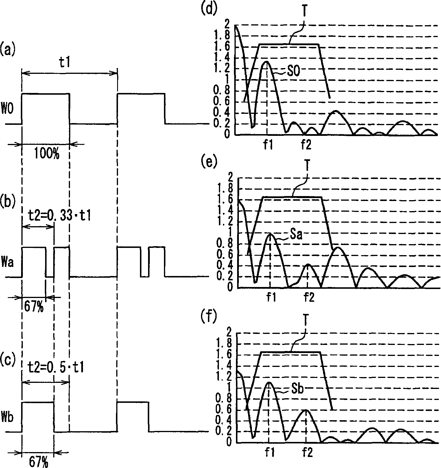
[0017] figure 2 In Embodiment 1 of the present invention, the relationship between the driving waveform generated by the waveform generating device, its frequency spectrum, and the frequency characteristics of the ultrasonic generating device is shown;
[0018] image 3 In Embodiment 1 of the present invention, the relationship between the driving waveform generated by the waveform generating device, its frequency spectrum, and the frequency characteristics of the ultrasonic generating device is shown, wherein the variable cycle t2 is set between the frequency bands of the ultrasonic generating device Inside;
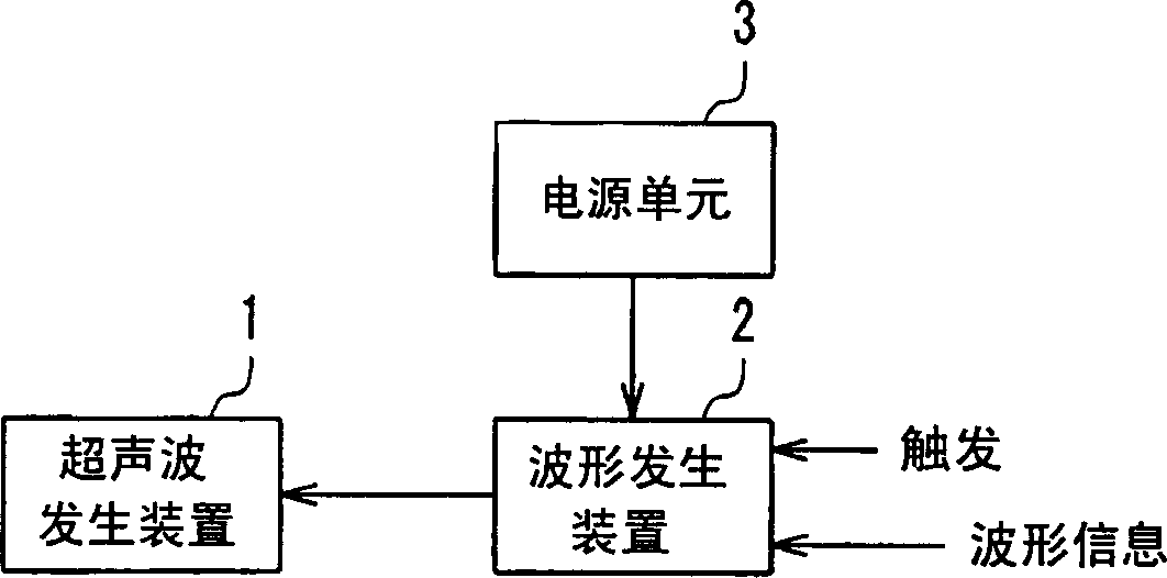
[0019] Figure 4 Shows a typical configuration block diagram of an ultrasonic diagnostic device according to Embodiment 2 of the present invention;
[0020] Figure 5 A block diagram showing a typical internal configuration of a waveform generating device in an ultrasonic diagnostic apparatus according to Embodiment 3 of the present invention;
[0021] Image 6 s...
Embodiment 2
[0039] Figure 4 A typical configuration block diagram of an ultrasonic diagnostic apparatus in Embodiment 2 of the present invention is shown.
[0040] exist Figure 4 Among them, the duty factor of the driving waveform generated by the waveform generating device 2 can be changed in order to control the sound power, which is similar to Embodiment 1. In this embodiment, according to the current mode information generated by the mode control unit 5, the waveform control unit 4 further determines the driving waveform to be generated by the waveform generating device 2 to correspond to the waveform information. For each mode, according to the current mode information to determine the waveform information.
[0041] Because of the given upper limit of the acoustic power, in B-mode and M-mode, which generally emphasize resolution, the peak value of the amplitude should increase as the wavenumber decreases. In Doppler mode (including two-dimensional Doppler mode), the emphasis is ...
Embodiment 3
[0045] Figure 5 A typical internal configuration block diagram of the waveform generating device 2 in the ultrasonic diagnostic apparatus in Embodiment 3 of the present invention is mainly given.
[0046] Figure 5 The waveform generating device 2 in can be applied to Embodiment 1 and Embodiment 2. Image 6 yes Figure 5 Waveform diagrams of signals at various sections in .
[0047] exist Figure 5 The middle waveform generating device 2 is composed of a basic waveform generating device 6 , a modulating wave generating device 7 , a multiplication device 8 and a driving device 9 .
[0048] Refer to the following Figure 5 with Image 6 The working principle of the waveform generating device 2 thus configured will be described. The basic waveform generating device 6 and the modulating wave generating device 7 are triggered by a trigger waveform A, and the waveforms output by these two devices are synchronized with each other. The basic waveform generator 6 generates a d...
PUM
 Abstract
Description
Claims
Application Information
 - R&D
- Intellectual Property
- Life Sciences
- Materials
- Tech Scout
- Unparalleled Data Quality
- Higher Quality Content
- 60% Fewer Hallucinations
Browse by: Latest US Patents, China's latest patents, Technical Efficacy Thesaurus, Application Domain, Technology Topic, Popular Technical Reports.
© 2025 PatSnap. All rights reserved.Legal|Privacy policy|Modern Slavery Act Transparency Statement|Sitemap|About US| Contact US: help@patsnap.com


