Smoke baffle
A technology of oily fumes and baffles, which is applied in the direction of removing oily fumes, household heating, lighting and heating equipment, etc. It can solve the problems of lowering kitchen grades, unsuitable large pots, and affecting thermal efficiency, so as to improve taste and grade, and improve absorption. The effect of oil smoke rate and warm environment
- Summary
- Abstract
- Description
- Claims
- Application Information
AI Technical Summary
Problems solved by technology
Method used
Image
Examples
Embodiment 1
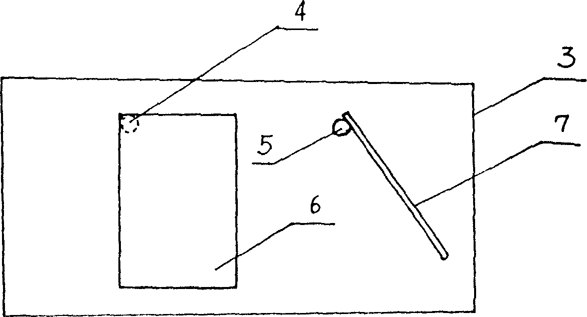
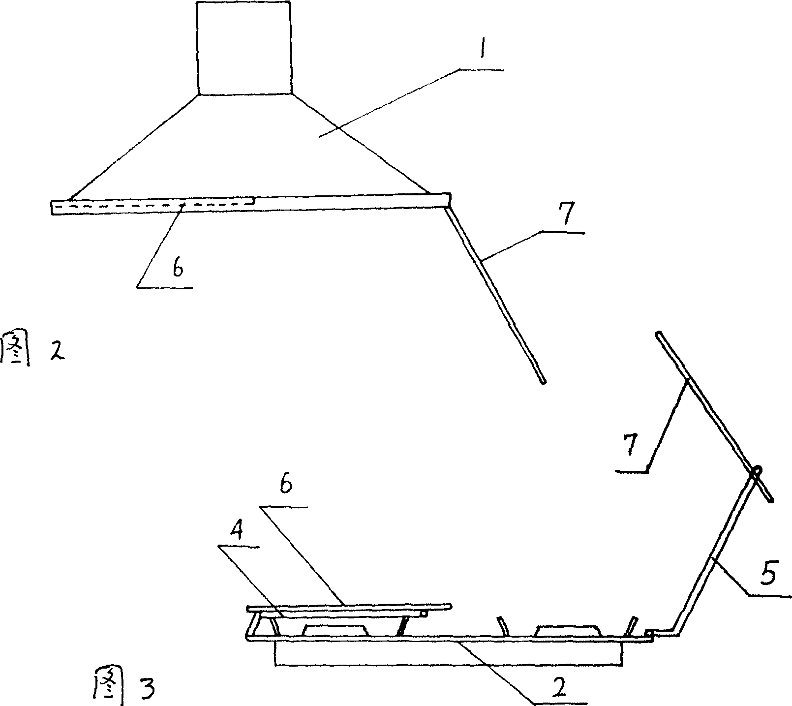
[0016] Embodiment 1: As shown in the figure, the length of the left and right guide baffles 6 and 7 is set as the distance between the cooker 2 and the range hood 1. It is best not to affect the opening, and the width is set to be the length of the range hood 1. 6, 7 of the left and right two guide baffles are connected with the left and right positioning devices 4, 5, and the left and right connecting positioning devices 4, 5 can adopt the tooth pressing positioning method, damping positioning method, etc., and then the left and right connecting positioning devices 4, 5 5 is connected with the wall, so that the two left and right guide baffles 6, 7 stand side by side between the range hood 1 and the cooker 2, and ensure that the two left and right guide baffles 6, 7 are centered on the left and right connecting positioning devices 4, 5 With the vertical direction as the axis, it can be rotated 180 degrees, and it can also be rotated 180 degrees in the direction vertical to the...
Embodiment 2
[0017] Embodiment 2: As shown in the figure, one side of the left and right guide baffles 6, 7 is connected with the left and right connecting and positioning devices 4, 5, and then the connecting and positioning devices 4, 5 are connected with the left and right lower parts of the range hood. The baffles 6, 7 are opened downwards. Make it between the range hood 1 stove 2, its angle can be adjusted and positioned arbitrarily, and the left and right guide baffles 6, 7 get final product when not in use. also reach
[0018] The application effect of the first embodiment.
Embodiment 3
[0019] Embodiment 3: As shown in the figure, the left and right guide baffles 6, 7 are connected to the cooker 2 through the left and right connection positioning devices 4, 5, and the left and right guide baffles 6, 7 are centered on the left and right connection positioning devices 4, 5 and the cooker 2 The long side is the axial direction, and the left and right guide baffles 6,7 can be set off backwards. The left and right guide baffles 6, 7 are centered on the left and right connecting positioning devices 4, 5 and the wide side of the cooker 2 is the axis direction. The angles of the left and right guide baffles 6, 7 can be adjusted and positioned arbitrarily. , to achieve the application effect of the first embodiment. When not in use, put down the left and right guide baffles 6,7 and get final product.
PUM
 Abstract
Description
Claims
Application Information
 - R&D Engineer
- R&D Manager
- IP Professional
- Industry Leading Data Capabilities
- Powerful AI technology
- Patent DNA Extraction
Browse by: Latest US Patents, China's latest patents, Technical Efficacy Thesaurus, Application Domain, Technology Topic, Popular Technical Reports.
© 2024 PatSnap. All rights reserved.Legal|Privacy policy|Modern Slavery Act Transparency Statement|Sitemap|About US| Contact US: help@patsnap.com


