
Drying oven of stenter setting machine

A stenter and oven technology, applied in drying, dryer, progressive dryer and other directions, can solve problems such as high energy consumption, and achieve the effects of stable machine operation, low requirements and energy saving

Active Publication Date: 2006-07-19
洪正凯
View PDF0 Cites 17 Cited by
  • Summary
  • Abstract
  • Description
  • Claims
  • Application Information

AI Technical Summary

Problems solved by technology

[0008] The invention solves the technical problem of high energy consumption in the prior art, and provides a stenter oven capable of saving energy and reducing consumption

Method used


Image

  • Drying oven of stenter setting machine
  • Drying oven of stenter setting machine

Examples


Embodiment Construction

[0021] Refer to attached figure 2 , the specific embodiment of the present invention will be described in detail.

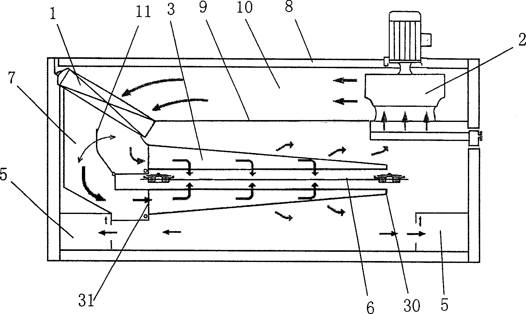
[0022] The schematic diagram of the side section structure of the stenter setting machine oven of this embodiment is as follows figure 2 Shown, be provided with cabinet 8, nozzle 3 is set in cabinet 8, fabric 6 floats thermally and bakes continuously through the gap between upper and lower nozzle 3, at the top of the cabinet outside the return air end 30 top of nozzle 3, set centrifugal Type circulating fan 2, heat exchanger 1 is arranged on the upper side of the inclination of the air inlet end 31 of nozzle 3, and the direction of inclination is to be inclined to the direction away from the fan. Below the space between them, a partition 9 is set between the nozzle 3, thereby forming a closed air duct 10 between the heat exchanger 1 and the centrifugal circulating fan 2, and only between the air inlet end 31 and the heat exchanger 1 Closed wind collection box...


PUM


Abstract

The oven of a setting stenter comprises a machine case (8) arranged a build-in nozzle (3) with a fresh-air end (31) and a return-air end (30), a fan (2) on side of end (30) to draw cold air, and a heat exchanger (1) on side of end (31); wherein, arranging an air channel (10) between one end of the (1) and exhaustion port of fan (2) and an air-collector (7) between another side of (1) and the end (31). This invention has low request to fan to prolong service time, and reduces heat energy loss and consumption and the cost.

Description

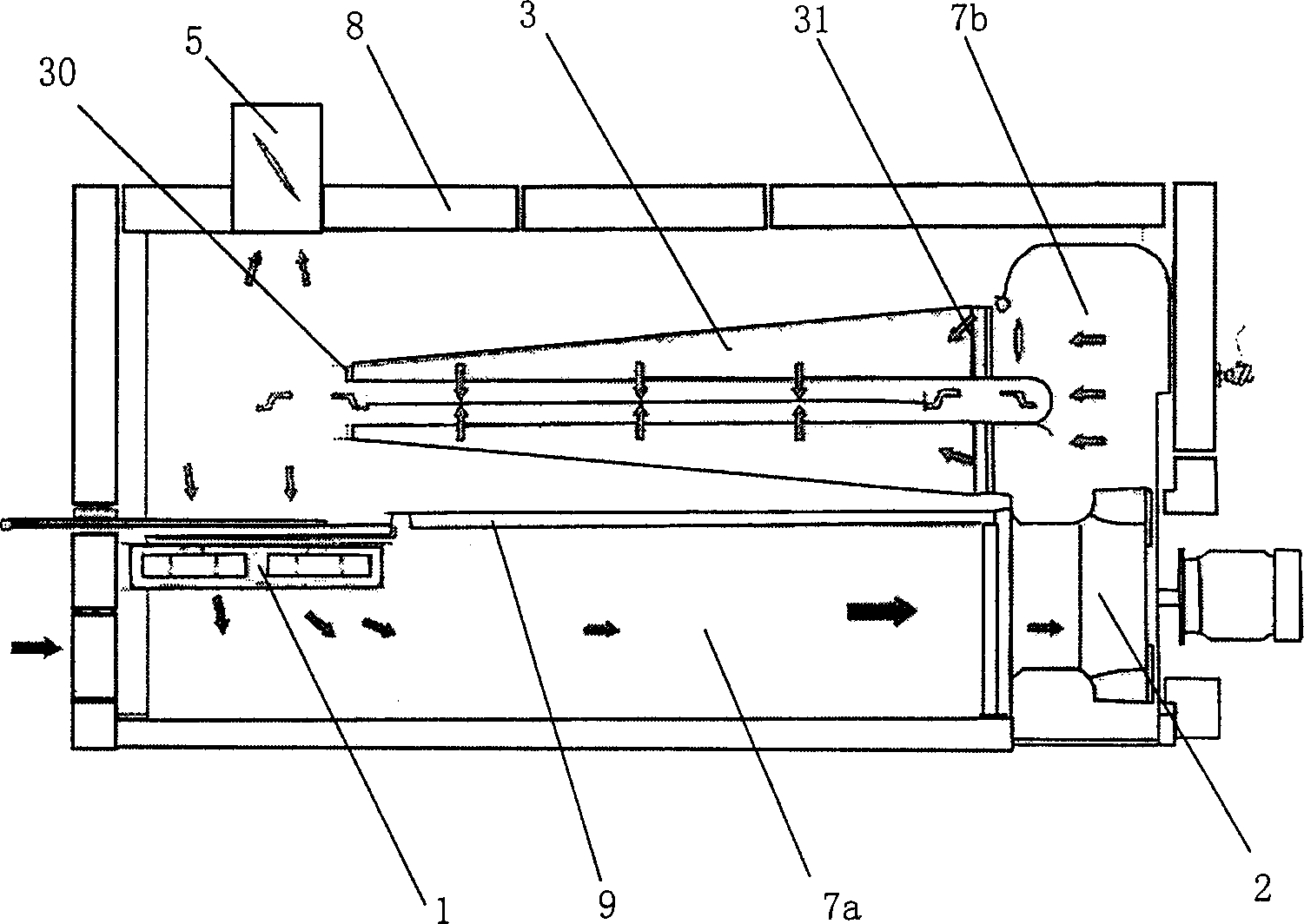
technical field [0001] The invention relates to an oven for a tenter setting machine. Background technique [0002] At present, in printing and dyeing and textile machinery, resin stenter setting machine is a common equipment and an important finishing equipment in dyeing and finishing equipment. It mainly performs dehydration, drying, stenter finishing and heat setting on fabrics. Wherein the parts used for drying are stenter setting machine oven (abbreviated as oven), and the schematic diagram of the side section structure of the existing oven is as follows: figure 1 As shown, a chassis 8 is mainly provided, and a heat exchanger 1, a centrifugal circulating fan 2, and a nozzle 3 are arranged in the chassis 8, and the fabric 6 is continuously floated and baked through the gap between the upper and lower nozzles 3, and is formed by figure 1 It can be seen that the nozzle 3 of the oven is arranged on the top of the oven, the centrifugal circulating fan 2 is arranged on the o...

Claims


Application Information

Patent Timeline
Patent Type & Authority Applications(China)
IPC IPC(8): D06C7/02F26B3/04F26B13/00
Inventor 洪正凯
Owner 洪正凯
Learn More