
Automatic focusing device

An autofocus and lens technology, which is applied in the direction of focusing devices, focusing devices, camera focusing devices, etc., can solve the problems of complex structure of the lens driving device and achieve the effect of simple structure

Inactive Publication Date: 2006-06-21
HONG FU JIN PRECISION IND (SHENZHEN) CO LTD +1
View PDF1 Cites 7 Cited by
  • Summary
  • Abstract
  • Description
  • Claims
  • Application Information

AI Technical Summary

Problems solved by technology

[0004] However, the lens driving device of the prior art changes the position of the lens through the action of the piezoelectric element to achieve the focusing function, because the device needs to be provided with a piezoelectric element at both ends of the lens barrel or at one end. An elastic element is provided at one end, so that the structure of the lens driving device is complicated

Method used


Image

  • Automatic focusing device
  • Automatic focusing device
  • Automatic focusing device

Examples


Embodiment Construction

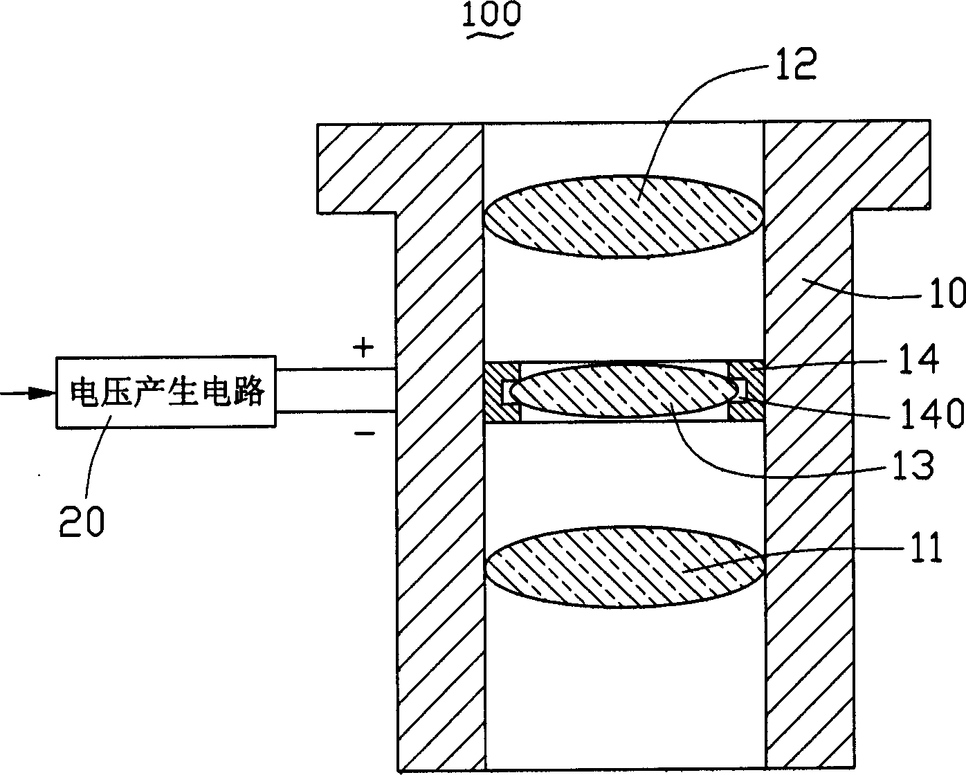
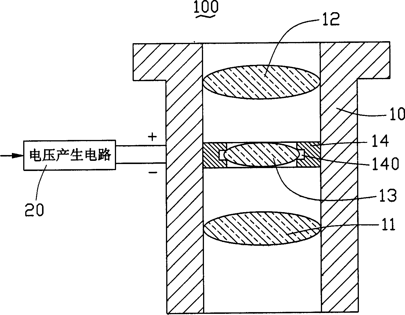
[0011] see figure 1 , figure 2 As shown, the autofocus device 100 of the present invention includes a lens barrel 10 and a piezoelectric element 14 .

[0012] The lens barrel 10 is provided with a first lens group 11, a second lens group 12 and a lens 13, the lens 13 is located between the first lens group 11 and the second lens group 12, the lens 13 is connected to the first lens group 11, the second lens group The two lens groups 12 can also be in other positional relationships.

[0013] The piezoelectric element 14 is a ring structure, its outer diameter is slightly smaller than the inner diameter of the lens barrel 10 , and a groove 140 is formed as a whole indented along the circumference, and the lens 13 is fixed in the groove 140 with glue. The piezoelectric element 14 can also be fixed in the lens barrel 10 by glue. The inner ring and the outer ring of the piezoelectric element 14 respectively have a positive electrode and a negative electrode connected to the volt...


PUM


Abstract

The invention discloses a self-focusing device, which contains lens tube and piezo element in the lens tube, wherein the lens tube is composed of the first lens group, second lens group and lens, which realizes the focusing function; the lens is contained in the piezo element, which connects the variable voltage circuit electrically.

Description

【Technical field】 [0001] The invention relates to an automatic focus device of a digital camera, in particular to an automatic focus device of a digital camera for electronic devices. 【Background technique】 [0002] Most of the optical modules of digital cameras used in electronic devices (such as mobile phones, PDAs, etc.) are fixed-focus designs, so they cannot realize the zoom function. In order to shoot farther objects, it is necessary to change the object distance, so the position of the lens needs to be adjusted. The focusing mechanism of a traditional digital camera generally uses a motor and a transmission mechanism to drive the lens to move to perform the focusing action. It needs to be equipped with a complex transmission mechanism to implement it. Used on smaller electronic devices. [0003] In the prior art, a piezoelectric element is used to drive the lens to achieve the focus of the camera. For example, U.S. Patent No. 4,601,539 discloses a lens moving device ...

Claims


Application Information

Patent Timeline
Patent Type & Authority Applications(China)
IPC IPC(8): G03B13/36H04N5/225
CPCG02B3/10G02B3/14G03B3/02G03B13/36
Inventor 余泰成
Owner HONG FU JIN PRECISION IND (SHENZHEN) CO LTD
Learn More