
RFID tag using a surface insensitive antenna structure

An antenna system and central axis technology, applied in the direction of the record carrier used by the machine, the mid-position feed between the antenna endpoints, the antenna, etc., can solve the problems of inconvenient manufacturing, expensive, and vulnerable

Active Publication Date: 2006-06-14
AVERY DENNISON CORP
View PDF2 Cites 4 Cited by
  • Summary
  • Abstract
  • Description
  • Claims
  • Application Information

AI Technical Summary

Problems solved by technology

The problem with such encapsulated RFID tags is that they are cumbersome, expensive, difficult to install, and protrude from the surface of the package to which they are installed, making them susceptible to damage and dropping during handling of the package, leaving the item unidentified
[0007] To overcome the problems described above, the RFID embodiments that have been developed have been to adhere or print the tag directly onto the package surface, resulting in a lower tag profile that is less likely to be damaged or dropped during handling of the package
However, direct surface mounting of these antennas or tags makes their efficiency susceptible to variations in the dielectric properties of the attached surface
Therefore, these systems require different markings to be used on different packages, thereby adding cost, complexity, and inconvenience to manufacture
Since each stored item is preferably individually labeled, many different labels are required, creating further problems

Method used


Image

  • RFID tag using a surface insensitive antenna structure
  • RFID tag using a surface insensitive antenna structure
  • RFID tag using a surface insensitive antenna structure

Examples


Embodiment Construction

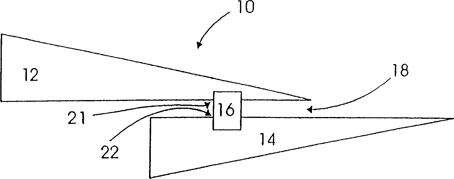
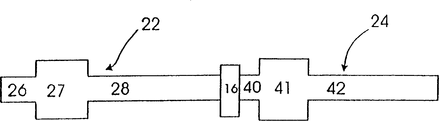
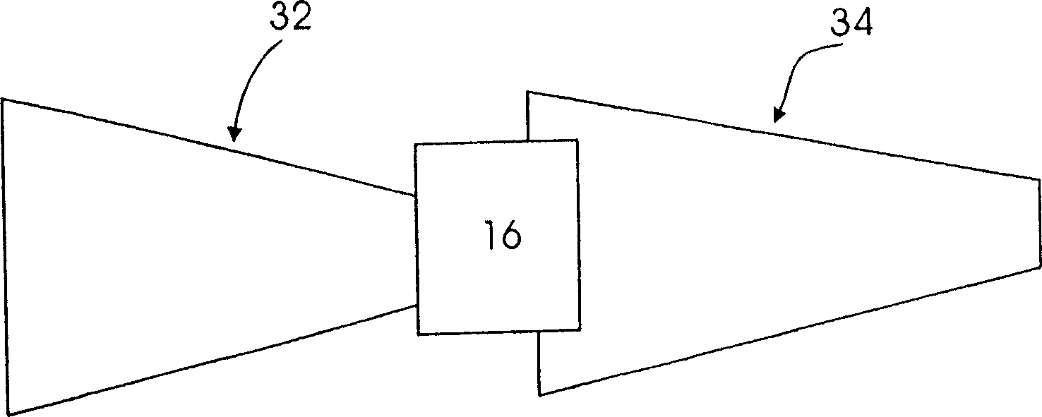
[0034] The present invention is directed to a radio frequency identification device (RFID) and its antenna system so that when the radio frequency identification device is attached to the package or container, it communicates information about the package or container to an external reader. The package may be an individual package containing a particular known item, or an outer package containing a group of further inner individual packages. The terms "package" and "container" may be used interchangeably herein to describe materials and equivalent structures that contain items such as goods or other individual packages. The present invention should not be limited to any particular meaning or method when "package" or "container" is used.

[0035] figure 1 One embodiment of the present invention implemented in an RFID tag 10 including a wireless communication device 16 is shown. Device 16 may be active, i.e. generate radio frequency energy (or radio energy) itself in response ...


PUM


Abstract

A surface-insensitive antenna system for use in an RFID tag having a wireless communication device includes a conductive tab coupled to the wireless communication device for receiving and radiating radio frequency energy. At least two of the fins are substantially identical in shape and are connected to the wireless communication device at a feed point, the feed point being positioned differently on each of the two fins, The width of the at least two fins taken along a direction transverse to the longitudinal center axis of each fin varies with the distance along the longitudinal center axis of each fin. Alternatively, the wireless communication device is connected to the fin at a feed point, the feed point being positioned differently on each of the fins, wherein each unit length along the longitudinal central axis of each fin The conductive area varies with distance along the longitudinal central axis.

Description

technical field [0001] The present invention relates to the field of radio frequency or radio frequency identification (RFID) tags and labels, and in particular to tags and labels including surface insensitive antenna structures. Background technique [0002] Current stocking and manufacturing methods rely on the ability to track and identify items of interest, such as inventory items, packages, individual parts, etc., and also rely on the ability to wirelessly communicate required item information for easy handling and use. One known method of tracking and providing desired item information is to attach wireless communication devices, such as active or passive transponders, to such items, thereby incorporating identification marks or tags capable of responding to radio frequency interrogations or commands. The tag may store or represent information about the attached item, such as a unique identification number, item status (eg, opened or unopened), location, and the like. ...

Claims


Application Information

Patent Timeline
Patent Type & Authority Applications(China)
IPC IPC(8): H01Q9/16G06K19/077H01Q1/22H01Q1/24H01Q1/38H01Q5/10H01Q9/04H01Q9/28H01Q9/40H01Q13/20H01Q23/00
CPCG06K19/07749G06K19/07771G06K19/07786H01Q1/2225H01Q1/38H01Q9/0407H01Q9/285H01Q9/40H01Q13/20H01Q23/00
Inventor I·J·福斯特
Owner AVERY DENNISON CORP
Learn More