
Substrate transfer device for thin-film deposition apparatus

A technology for conveying substrates and films. It is used in conveyor objects, transportation and packaging, and gaseous chemical plating. It can solve problems such as poor maintenance performance, increased cost, and narrow spacing.

Inactive Publication Date: 2006-06-07
IHI CORP
View PDF2 Cites 2 Cited by
  • Summary
  • Abstract
  • Description
  • Claims
  • Application Information

AI Technical Summary

Problems solved by technology

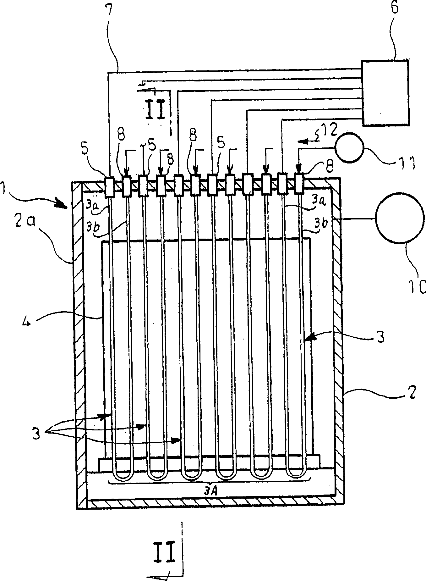
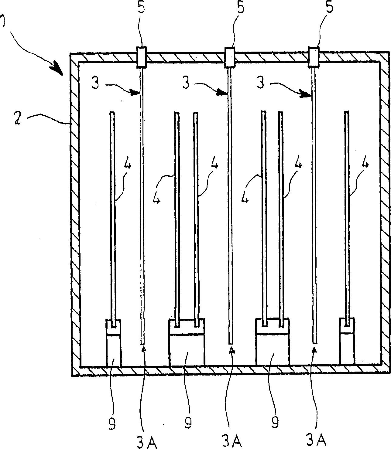
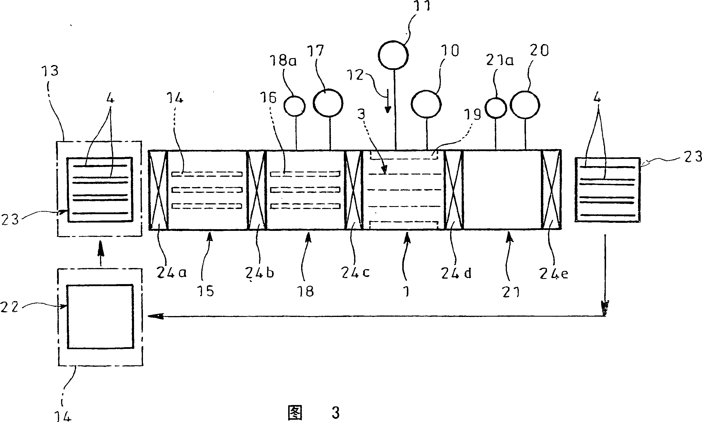
[0026] However, as described above, in order to prevent the plasma generated by the inductive coupling type electrode 3 from going around the back side of the substrate 4, a large mask plate 35 covering the entire outer peripheral portion of the substrate 4 is indispensable, and it must be covered. The gap between the substrate 4 and the substrate 4 is kept to a minimum, but it is difficult to move such a large mask plate 35 in the film formation chamber 1 with high precision, and there is a disadvantage of increasing the cost.
[0027] In addition, there is a risk that a thin film such as a silicon film adheres to the surface of the mask plate 35 and prevents the thin film from being uniformly formed on the substrate 4 due to falling of the film. film work on
However, since the interval between the mask plate 35 and the inductive coupling type electrode 3 is narrow, the removal operation cannot be efficiently performed, and its maintenance performance is not good.

Method used


Image

  • Substrate transfer device for thin-film deposition apparatus
  • Substrate transfer device for thin-film deposition apparatus
  • Substrate transfer device for thin-film deposition apparatus

Examples


Embodiment Construction

[0050] Embodiments of the present invention will be described below with reference to the drawings.

[0051] Figure 6 ~ Figure 11 An example of the present invention is shown. In the figure, with Figure 3~ Figure 5 Parts using the same reference numerals represent the same parts, and its basic structure is the same as that shown in Fig. 3- Figure 5 The same goes for the prior art shown. However, this embodiment is characterized in that, as Figure 6 ~ Figure 11 As shown, on the transport trolley 23, a partition wall plate 37 formed with an opening 36 larger than the substrate 4 and facing the inductive coupling type electrode 3 is erected, and a partition wall plate 37 away from the inductive coupling type electrode 3 is provided. On one side, a photo frame-shaped substrate holder 38 on which the substrate 4 is mounted is disposed such that the substrate 4 is disposed substantially in the center of the opening 36 of the partition wall plate 37 and the outer periphery of...


PUM


Abstract

The present invention is a substrate conveying device of a thin film forming apparatus, in order to achieve the following purpose, that is, a large mask plate (35) that covers the entire outer peripheral portion of a substrate (4) is not provided in a film forming chamber (1), It can reliably prevent the plasma generated from the electrode (3) from going around the back side of the substrate (4), and can reduce costs and improve maintenance performance. 4) the opening portion (36) and the partition wall plate (37) opposite to the inductively coupled electrode (3), and the side of the partition wall plate (37) away from the inductively coupled electrode (3) is configured with a A picture frame-shaped substrate holder (38) for the substrate (4), such that the substrate (4) is disposed at approximately the center of the opening (36) of the partition wall (37) and at the outer peripheral edge of the substrate holder (38) Covered by a bulkhead (37).

Description

technical field [0001] The present invention relates to a substrate transfer device of a thin film forming device using plasma CVD for uniformly forming a thin film of silicon or the like on a substrate. Background technique [0002] As a clean energy source, solar cells have been attracting people's attention and expectations, and cost reduction is an indispensable factor to realize its popularization. For this reason, a thin film forming apparatus capable of forming a silicon film with a uniform film thickness on a large substrate and forming a silicon film on a plurality of substrates in one operation, thereby enabling mass production, has been desired. When forming a thin film such as a silicon film, a parallel plate type (capacitive coupling type) plasma CVD device is used, but usually only one substrate can be processed, so its processing capacity is low. On the other hand, if multiple substrates are processed at the same time , there will be a problem that the device...

Claims


Application Information

Patent Timeline
IPC IPC(8): B65G49/06H01L21/205C23C16/44C23C16/54H01L21/677H01L21/68H01L31/04
CPCC23C16/042C23C16/4587C23C16/54H01J37/32541H01J37/32743H01L21/67712H01L21/67754H01L21/6776H01L21/68728
Inventor 山崎秀作长谷川敬晃
Owner IHI CORP
Learn More