Method for providing an internet-layer address to a client device

A technology of the Internet layer and client equipment, applied in the direction of data exchange network, digital transmission system, electrical components, etc., can solve the problem that the relay equipment cannot monitor the business relatively sufficiently

Inactive Publication Date: 2006-06-07
ALCATEL LUCENT SAS
View PDF2 Cites 6 Cited by
  • Summary
  • Abstract
  • Description
  • Claims
  • Application Information

AI Technical Summary

Problems solved by technology

As a result, some future messages sent from the client device to the service device no longer need to pass through the relay device, in which case the relay device cannot relatively adequately monitor said traffic

Method used


Image

  • Method for providing an internet-layer address to a client device
  • Method for providing an internet-layer address to a client device
  • Method for providing an internet-layer address to a client device

Examples


Embodiment Construction

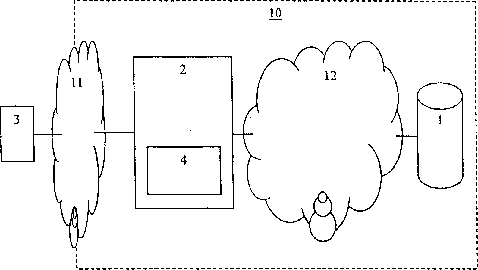
[0070] figure 1 The network 10 shown comprises a service device 1, such as a server, coupled by, for example, an Internet Protocol network 12, to a network device 2 according to the invention, such as a network device comprising a relay device 4 according to the invention. router. The network device 2 is coupled to a client device 3, eg a personal computer or a modem and also referred to as a client device or host, via a local area network 11, eg Ethernet. The server includes, for example, a dynamic host configuration server, and the client device includes, for example, a dynamic host configuration client device.

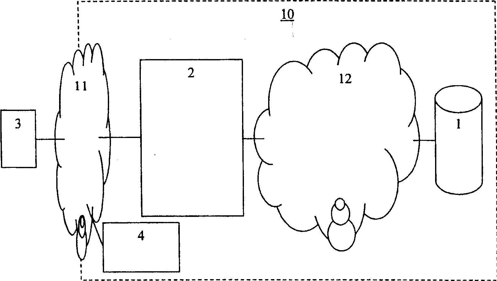
[0071] figure 2 The network 10 shown corresponds to, among other things figure 1 Network 10 is shown: the relay device 4 is now located outside the network device 2 and is coupled to the network device 2 and the client device 3 via eg a local area network 11 .

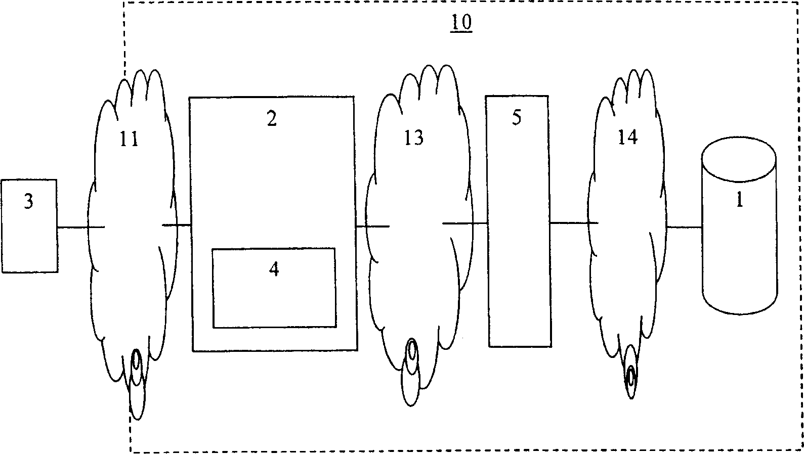
[0072] image 3 The network 10 shown comprises a service device 1 , for example a server coupled to...


PUM


Abstract

A method for providing an Internet layer address from a service device to a client device through a relay device, the method comprising the following steps on the relay device: receiving a first message from the client device and receiving a second message from the service device; sending Another first message is sent to the service device and another second message is sent to the client device. In order to allow the relay device to relatively adequately monitor a certain service, the method is provided on the relay device with the step of inserting the Internet layer address defining the relay device into a high-level field of another second message, said high-level field Originally designed to identify service devices. As a result, future messages sent from the client device to the serving device must pass through the relay device. The high-level fields include the server Internet Protocol address field and the option-54 field. Dynamic host configuration protocol messages are discover, offer, request, acknowledge, and request and/or update and/or release messages.

Description

technical field [0001] The present invention relates to a method for providing an Internet layer address from a service device to a client device through a relay device. The method includes the following steps on the relay device: [0002] - receiving a first message from the client device, and sending another first message to the service device, said first message comprising an Internet layer address and a lower layer address; and [0003] - receiving a second message from the serving device and sending another second message to the client device, said second message comprising an Internet layer address, a lower layer address and a higher layer field for identifying the serving device. [0004] - An example of said service device is a server, an example of said relay device is a repeater, an example of said client device is a personal computer and / or a modem. Background technique [0005] Prior art methods are well known and define a client device to generate a first messa...

Claims


Application Information

Patent Timeline
Patent Type & Authority Applications(China)
IPC IPC(8): H04L29/12H04L12/58
CPCH04L61/5014H04L67/561
Inventor D·L·F·戈特曼N·A·A·让森斯
Owner ALCATEL LUCENT SAS
Why Eureka
Try Eureka