
Laser cutting head

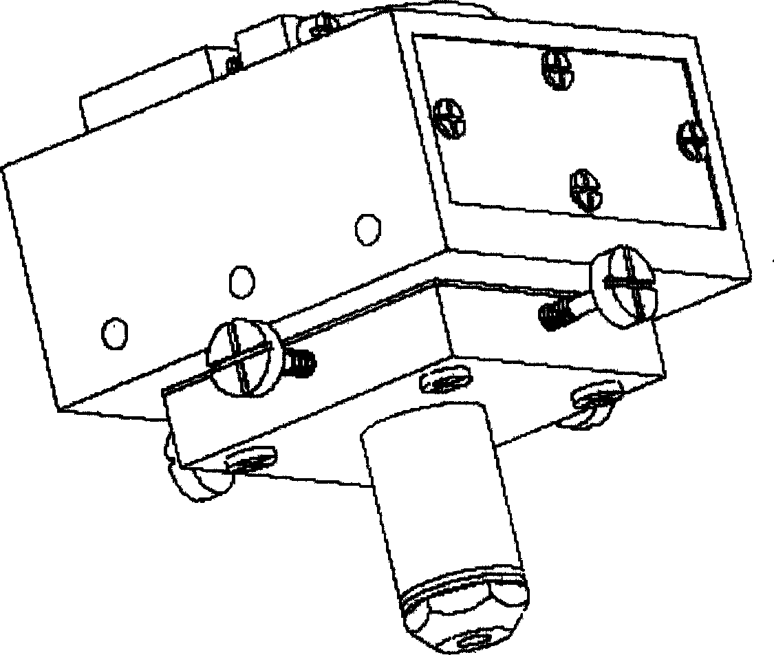
A laser cutting head, a new type of technology, used in laser welding equipment, welding equipment, metal processing equipment, etc.

Inactive Publication Date: 2006-05-24
JIANGSU UNIV
View PDF0 Cites 9 Cited by
  • Summary
  • Abstract
  • Description
  • Claims
  • Application Information

AI Technical Summary

Problems solved by technology

[0003] The invention provides a new type of laser cutting head to overcome the defects caused by the current traditional laser cutting head

Method used


Image

  • Laser cutting head
  • Laser cutting head
  • Laser cutting head

Examples


Embodiment 1

[0041] Example 1 Newly designed cutting head equipped with supersonic nozzles for cutting galvanized sheets

[0042]The nozzle design Mach number is 1.5, the theoretical gas supply pressure is 4bar, the thickness of the galvanized sheet is 1mm, the cutting gas is nitrogen, the gas supply pressure is 5bar, and when the cutting speed is 4.8m / min, the cut end surface is very bright, and the galvanized layer is There is almost no damage at the incision, only 0.2mm wide remelted and solidified galvanized layer; there is no dross in the lower layer of the incision; the roughness of the incision end face is Ra=2.4812μm.

[0043] cutting speed

[0044] It can be seen from the above results that the laser cutting with the new continuous supersonic nozzle has fast cutting speed and good cutting quality. At the same time, when the distance from the nozzle to the upper surface of the workpiece is large, the cutting quality is still good, which is difficult for traditional laser ...

Embodiment 2

[0045] Example 2 Using high-pressure nitrogen to cut stainless steel

[0046] cutting speed

(m / min)

Surface roughness

(mm)

Lower surface seam width

(mm)

Tilt angle

(°)

Dross

roughness

Ra(μm)

2.0

0.20

0.15

0.716

rare

3.1

2.5

0.19

0.13

0.859

No

1.7

3.0

0.18

0.12

0859

rare

2.8

[0047] The cutting quality of the above-mentioned groups of experiments is relatively good. The incision width on the upper and lower surfaces is small, and the inclination angle is also small, the verticality of the incision is high, the incision section is smooth, and the roughness Ra is small.

[0048] Cutting 5mm thick stainless steel plate, the brand is 304 (1Cr18ni9), the laser power is 2000W, the distance between the nozzle and the workpiece is 1.2mm, nitrogen is used as the cutting gas, the gas supply pressure is 8bar, an...


PUM


Abstract

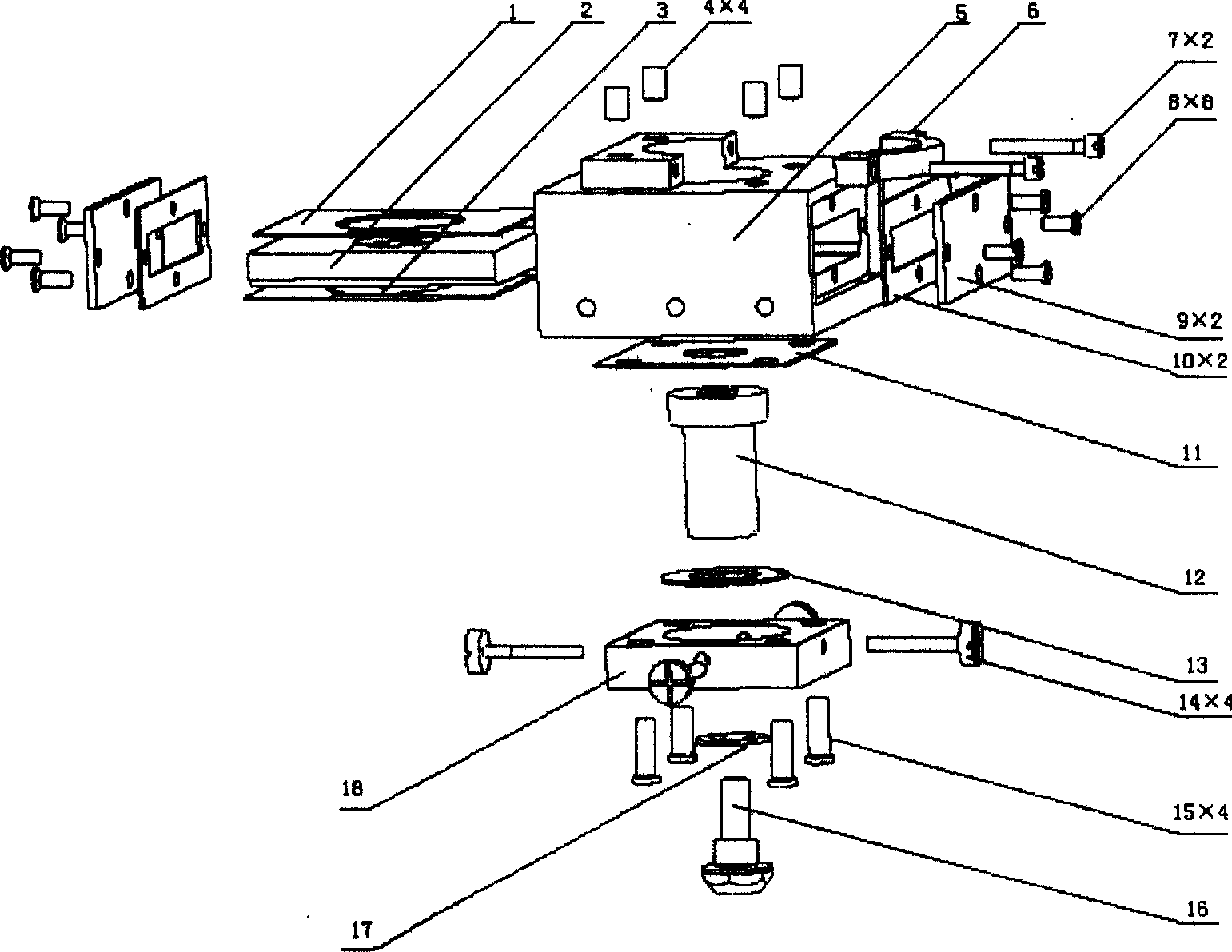
The present invention provides a new-type gas-aided laser cutting head. The mounting mode of said laser cutting head lens seat adopts a plug-in type V-shaped groove structure, it can be applicable to lenses with different focal distances, and the axiality of the laser beam and nozzle can be regulated by adopting four-point regulation method, and its cutting nozzle adopts a newly-designed supersonic nozzle.

Description

technical field [0001] The invention relates to the technical field of laser cutting, in particular to a new type of laser cutting head, which can be used for thin plate and three-dimensional cutting. The auxiliary gas can be oxygen, nitrogen, carbon dioxide or inert gas. Background technique [0002] At present, the traditional laser cutting head adopts a serial structure, that is, the lens holder can only be taken out after the cutting head is completely disassembled. The installation and removal of the lens holder and the maintenance of the lens are very inconvenient, which wastes processing time and reduces processing efficiency. The adjustment method to maintain the coaxiality of the laser beam and the nozzle: "3+1" structure, that is, there are three adjustment screw support points in the same direction, and the other support point is on the opposite side of the direction. This structure is more complicated and troublesome to adjust; Two mutually perpendicular directio...

Claims


Application Information

Patent Timeline
IPC IPC(8): B23K26/064B23K26/38
Inventor 王霄杨波刘会霞蔡兰
Owner JIANGSU UNIV
Learn More