Energy recovering device

An energy recovery device and initial charging technology, applied in identification devices, televisions, instruments, etc., can solve the problem of high cost of energy recovery circuits and achieve the effect of saving costs

Inactive Publication Date: 2006-05-17
NANJING LG TONGCHUANG COLOR DISPLAYS SYST CO LTD
View PDF0 Cites 1 Cited by
  • Summary
  • Abstract
  • Description
  • Claims
  • Application Information

AI Technical Summary

Problems solved by technology

In this way, the cost of constituting the energy recovery circuit is relatively high, which is its shortcoming

Method used


Image

  • Energy recovering device
  • Energy recovering device
  • Energy recovering device

Examples


Embodiment Construction

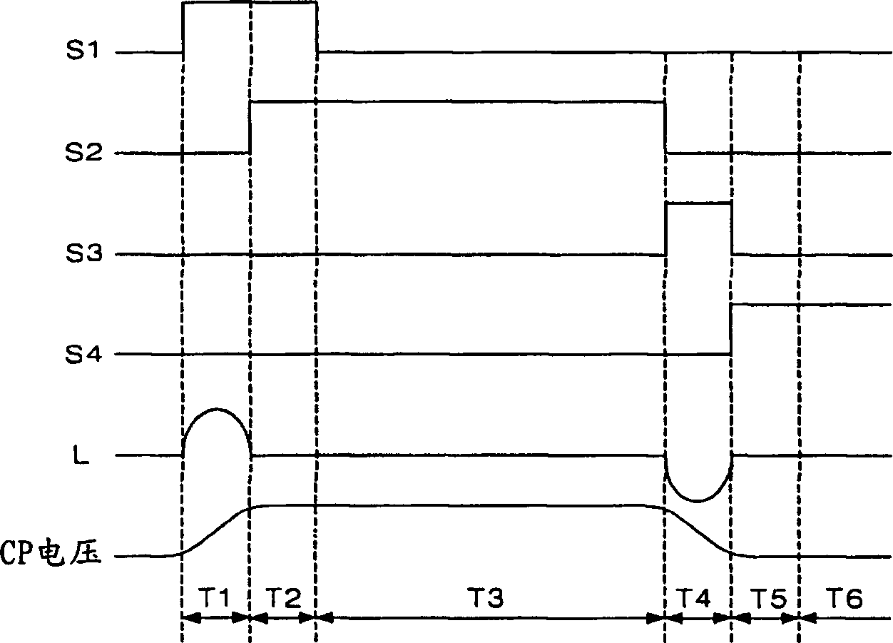
[0052] Below, will refer to Figure 5 to Figure 9 Embodiments of the energy recovery device according to the present invention will be described in detail.

[0053] Figure 5 It is a schematic diagram showing the energy recovery device according to the first embodiment of the present invention.

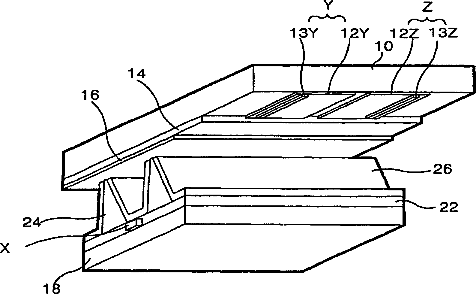
[0054] The energy recovery device of the present invention is applied to a plasma display having a scan electrode Y, a sustain electrode Z and an address electrode X ( figure 1 shown).

[0055] refer to Figure 5 It can be seen that the energy recovery devices 60 and 62 and the plate capacitor Cp according to the first embodiment of the present invention are arranged symmetrically with each other. Here, the plate capacitance Cp represents the capacitance formed between the scan electrode Y and the sustain electrode Z equivalently. The first energy recovery device 60 supplies the sustain pulse to the scan electrode Y, and the second energy recovery device 62 and the first energy r...


PUM


Abstract

An energy recovery device consists of plate capacity formed by equivalence between scan electrode and maintenance electrode, source capacity for carrying out recovery charging on voltage charging to plate capacity, maintenance voltage source for supplying maintenance voltage to plate capacity and initial charging voltage source for supplying initial charging voltage to source capacity. It features that initial charging voltage value is applied to carry out charging on source capacity in order to decrease rated voltage of switching component.

Description

(1) Technical field [0001] The present invention relates to the technology of energy recovery device. In particular, it relates to an energy recovery device and method capable of reducing costs. (2) Background technology [0002] Recently, some flat-panel display devices have been successively developed, all of which have better overcome some shortcomings of the cathode ray tube (Cathode ray tube), such as reducing its thickness and volume. [0003] Such flat display devices include: liquid crystal display (Liquid Crystal Display: LCD), field emission panel (Field Emission Display: FED), plasma display (Plasma Display Panel: PDP, hereinafter referred to as PDP), and cathode ray emission (Electro-Luminescence: EL) flat panel display (panel), etc. [0004] Among them, the PDP is a display element using gas discharge, which has the advantage of being suitable for a large flat panel display (panel). Such as figure 1 As shown, the 3-electrode AC surface discharge PDP that has...

Claims


Application Information

Patent Timeline
Patent Type & Authority Applications(China)
IPC IPC(8): G09F9/313G09G3/288H01J17/49H04N5/66
Inventor 金泰亨
Owner NANJING LG TONGCHUANG COLOR DISPLAYS SYST CO LTD
Why Eureka
Try Eureka