Electromagnetic wave shielding coating selective spraying apparatus

A technology for shielding coatings and spraying devices, applied to spraying devices, devices for coating liquid on surfaces, coatings, etc., can solve problems such as inability to improve efficiency, difficulty in casting, and loosening of nut holes in aluminum machine tools 102

Inactive Publication Date: 2006-05-17
夏在基
View PDF0 Cites 0 Cited by
  • Summary
  • Abstract
  • Description
  • Claims
  • Application Information

AI Technical Summary

Problems solved by technology

[0008] Since this invention is provided with a plurality of closed parts 132, closed part support platforms 133, and open parts 131 on the jig 103, and is integrated with the jig 103, it is very convenient not only for revision operations such as design changes during production or after production. It is inconvenient, and when using the clamp 103 integrally formed with a plurality of open parts 131, closed part 132 and closed part support platform 133, if a certain specific position is to be repaired, it will be stopped for a long time with the clamp 103 as an intermediate tool. The entire spraying production process of shielding coatings such as mobile phones will cause great losses to production
[0009] In addition, before mass production of mobile phones, samples need to be produced by fixture 103, and mobile phones usually consist of front cover (front cover) 61, rear cover (rear cover) 62, upper cover (upper cover) 63, lower cover (lower cover) 64. A dummy plate (dummy plate) 65 is used to spray the electromagnetic wave shielding coating with corresponding fixtures 103 for each component. For the production of a small number of samples before mass production, the efficiency cannot be improv

Method used


Image

  • Electromagnetic wave shielding coating selective spraying apparatus
  • Electromagnetic wave shielding coating selective spraying apparatus
  • Electromagnetic wave shielding coating selective spraying apparatus

Examples


Embodiment Construction

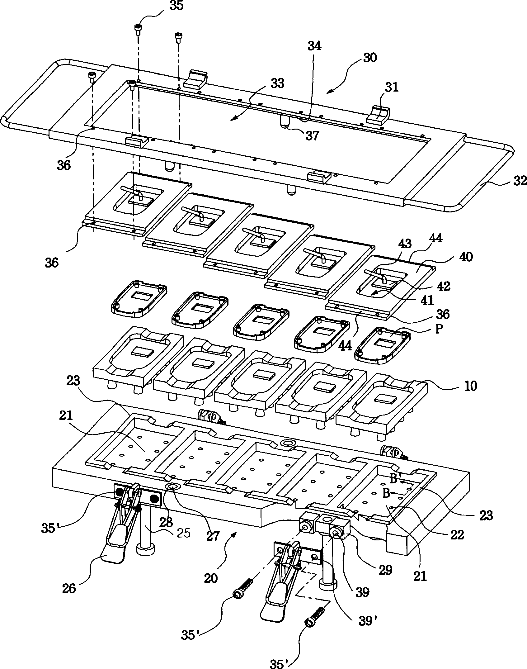
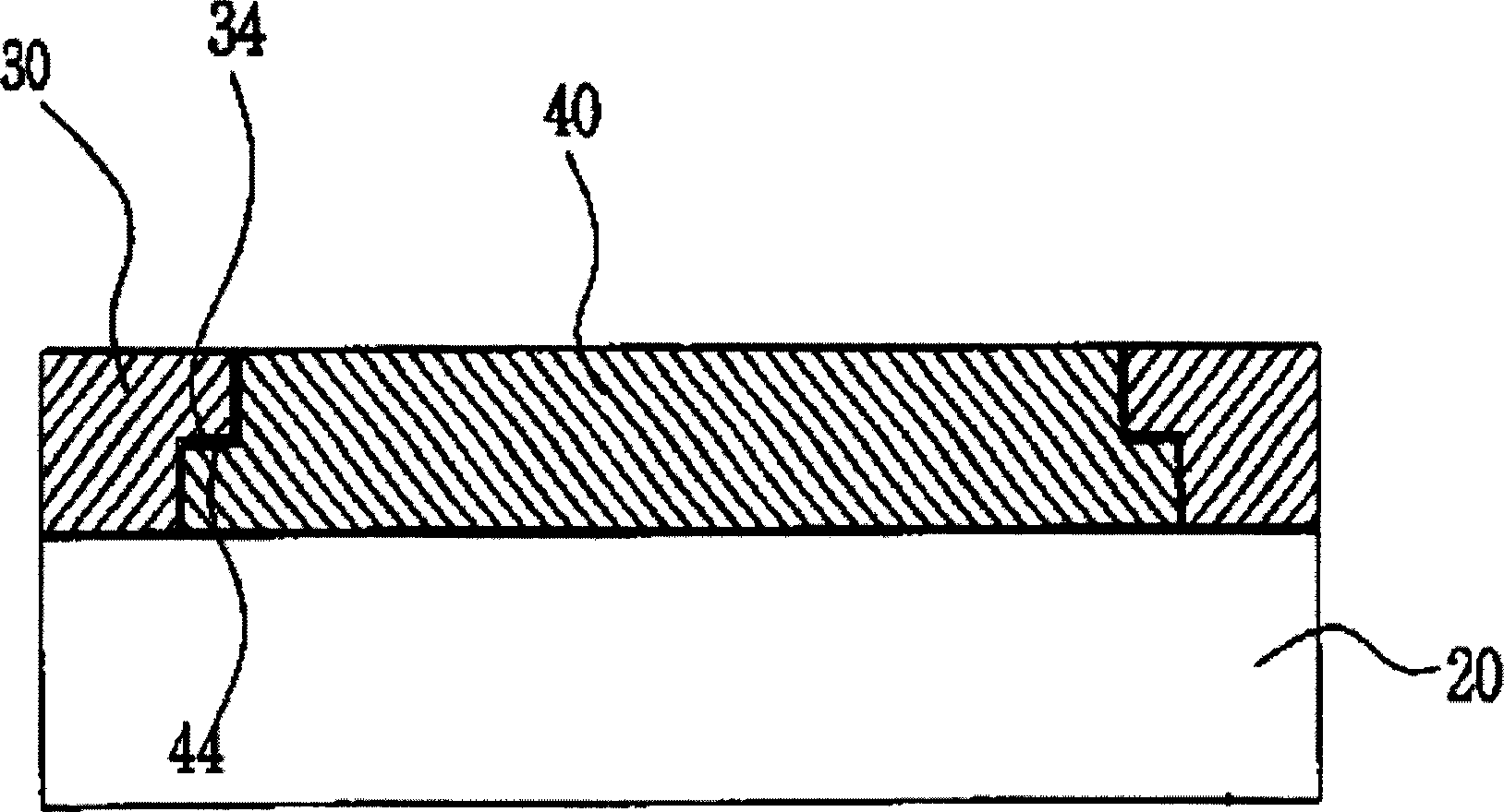
[0042] Hereinafter, the present invention will be described in detail with reference to the accompanying drawings.

[0043] figure 1 is a perspective view of the present invention, figure 2 It is an exploded perspective view of the present invention, image 3 yes figure 1 A sectional view taken along the line A-A', Figure 4 yes figure 2 The sectional view taken along the line B-B', Figure 5 It is the front view of the present invention, Figure 6 It is a side view of the present invention, Figure 7 yes figure 1 The sectional view cut along C-C ' line shows the use state of the present invention, Figure 8 It is a schematic diagram of the inner wall of the mobile phone body casing (P) completed by the present invention, Figure 9 It is a schematic diagram of the combination state of mobile phone parts as the object of the present invention, Figure 10 It is a schematic diagram of the use state of setting each component of the mobile phone on the jig of each co...


PUM


Abstract

The invention relates to an electromagnetic wave shielding paint selective spraying device having a jig including a plurality of individually detachable core plates, a machine tool (20) made of a plurality of silicone resin molds (10) for housing a mobile phone body shell (P), synthetic resin material ) and fixtures. Wherein, the machine tool (20) has a plurality of silicone resin injection grooves (21), the silicone resin injection groove has a plurality of exhaust holes (22) with a narrow upper and a wider lower structure, and the bottom of the machine tool has 4 support rods (25 ), a pair of pads (29) with a plurality of nut holes (39) are respectively inserted on both sides; a pair of clamping plates (31) are formed on both sides above the clamp, and a pair of clamping plates (31) are formed in the center along the quadrilateral periphery on the back side. The opening (33) of the lower step (34) of each screw hole (36), a plurality of core plates (40) with an open portion (41), a closed portion (42) and a closed portion support platform (43) are arranged up and down with a The upper steps (44) of a plurality of screw holes (36) are connected to the screw holes 36 by screws.

Description

technical field [0001] The invention relates to an electromagnetic wave shielding paint selective spraying device with a plurality of clamps that can be independently detached core boards, which can selectively spray electromagnetic wave shielding paint on the inner walls of various mobile phone fuselages to completely shield electromagnetic waves and prevent internal circuit failures of the machine at the same time. Specifically, a silicone resin mold for accommodating the mobile phone body casing is formed, and a plurality of core plates having an open part, a closed part, and a closed part support platform are combined with screws to form a clamp at the lower side of the opening part formed above, so that It can be connected with the top of the machine tool made of synthetic resin material and the silicone resin mold, and can selectively spray the inner wall of the mobile phone body shell, and inject liquid silicone resin through the silicone resin injection groove above the...

Claims


Application Information

Patent Timeline
IPC IPC(8): B05C13/00
CPCB05B12/20B05B13/02
Inventor 夏在基
Owner 夏在基
Why Eureka
Try Eureka