Eureka AIR delivers breakthrough ideas for toughest innovation challenges, trusted by R&D personnel around the world.

Internal barrel water-discharging structure of water-saving wave wheel type or stirring type full-automatic washing machine

A fully automatic washing machine and pulsator-type technology, which is applied to other washing machines, washing devices, textiles and papermaking, etc., and can solve the problems of easy swelling, easy leakage, easy water leakage, etc.

Active Publication Date: 2006-05-10
JINLING ELECTRICAL CO LTD
View PDF6 Cites 28 Cited by
  • Summary
  • Abstract
  • Description
  • Claims
  • Application Information

AI Technical Summary

Problems solved by technology

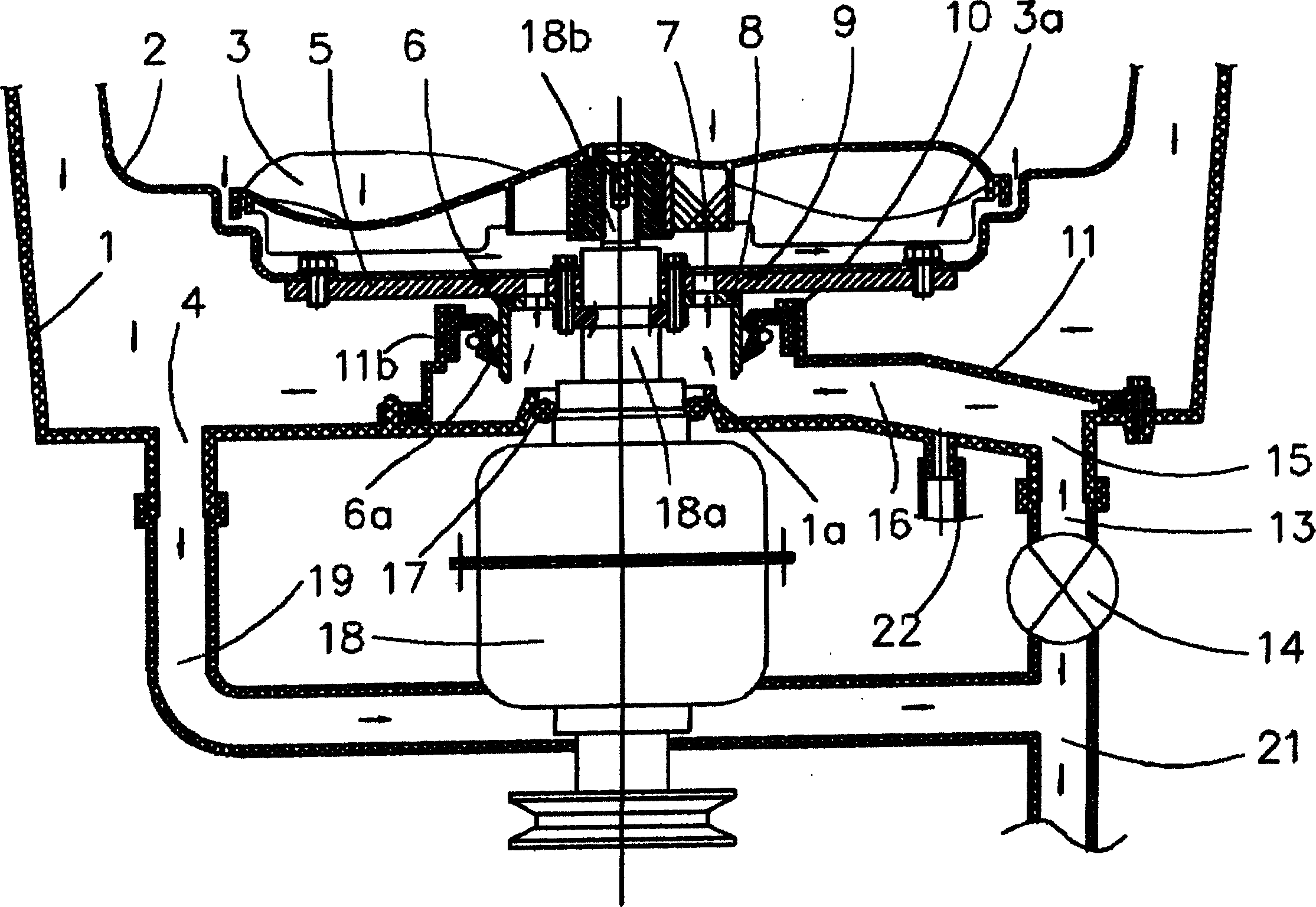
The deficiencies of this prior art include: the sealing pressure of the buoyancy is difficult to be large, especially when the water injection speed is slow, it is easy to leak; the suction effect of the wave wheel rotation on the bottom rib will destroy the sealing effect of the buoyancy
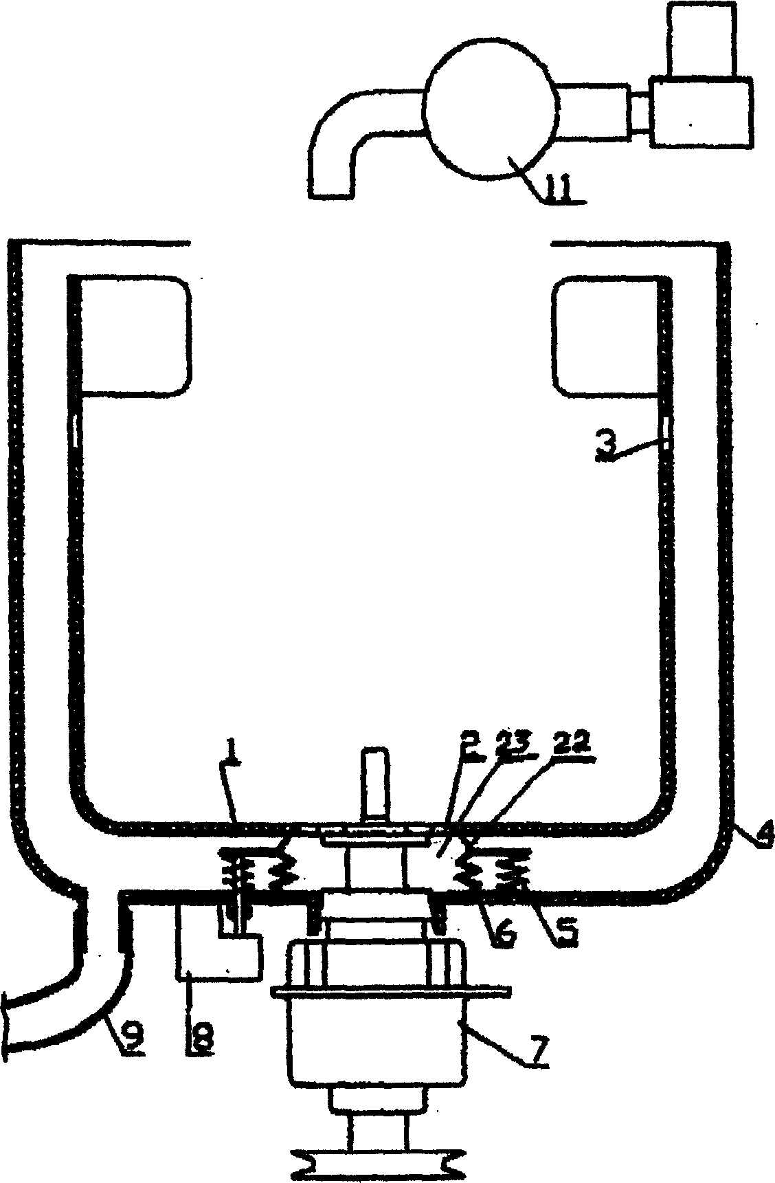
This prior art uses power to drive the isolation structure, which is more reliable than buoyancy sealing, and also has the function of controlling drainage of the whole machine, but it also has shortcomings, including: the cylindrical bellows of the valve core 6 bears high water pressure and is easy to swell; The bottom of the spool 6 needs to be quite airtight and firmly fixed on the inner bottom of the outer tub 4 to prevent water leakage
[0006] The common deficiency of the above three existing technologies is that there is a water storage cavity between the outer bottom of the inner bucket and the inner bottom of the outer bucket, the water in the cavity is obviously wasted, and it is easy to leak

Method used


Image

  • Internal barrel water-discharging structure of water-saving wave wheel type or stirring type full-automatic washing machine
  • Internal barrel water-discharging structure of water-saving wave wheel type or stirring type full-automatic washing machine
  • Internal barrel water-discharging structure of water-saving wave wheel type or stirring type full-automatic washing machine

Examples


no. 1 Embodiment

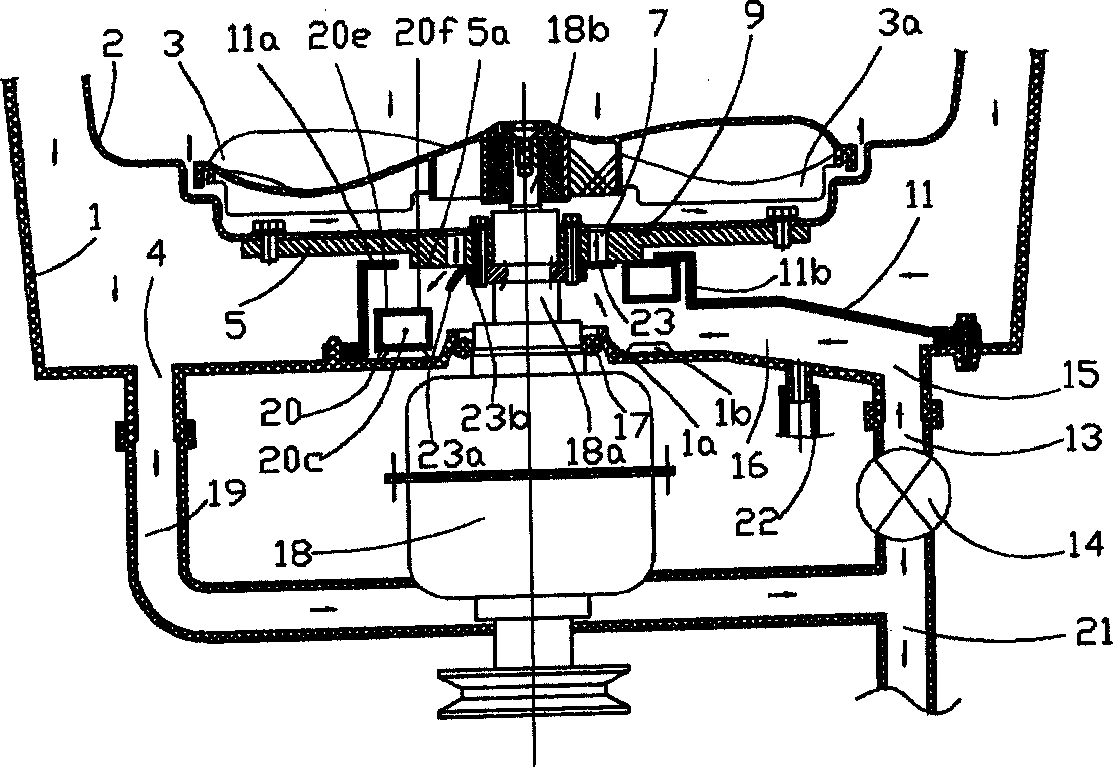
[0021] The structure of the drain valve in the washing machine in the first embodiment of the present invention is as follows: Figure 4 shown. This structure is improved on the basis of the pulsator type or agitator type fully automatic washing machine of the prior art, and the parts similar to the prior art include: the upper shell shaft fixing part of the deceleration clutch 017 driven by the motor through the pulley is covered with a sealing ring Fixed in the center hole of the outer barrel 005; the inner barrel 008 set in the outer barrel 005 is fixed on the dehydration shaft 015 through the tray, the inner barrel 008 has no holes in the side wall of the lower part, and there is a circle of dehydration outlet holes in the upper part and the bottom is distributed in the inner barrel 008 The axis of rotation is the drain hole 011 in the center of a ring; the dehydration shaft 015 also has a coaxial washing shaft 014 for connecting the pulsator 013. The main improved design...

no. 2 Embodiment

[0027] The structure of the drain valve in the washing machine in the second embodiment of the present invention is as follows: Figure 5 As shown (the meaning and function of the symbols in the figure not explained in the text are the same as Figure 4 the same). The structure is the same as Figure 4 The difference of the first embodiment shown is mainly that in the axial cam pair composed of the sealing plate 112 and the lifting boss ring 109 inserted around the cylinder of the tray, the driven teeth 119 are formed on the sealing plate 112 instead; and, The central part of the sealing plate 112 is changed to slide and rotate with the cylindrical surface, and the lifting boss ring 109 is fixed to the bottom of the outer barrel 105 instead of rotating. In this way, when the driven tooth 119 is driven by the main driving tooth 007, the sealing plate 112 rotates up and down around the cylindrical surface, separates and closes with the sealing ring 010, and produces the same c...

no. 3 Embodiment

[0029] In the third embodiment of the present invention, the structure of the drain valve in the inner tub of the washing machine is as follows: Figure 6 As shown (the meaning and function of the symbols in the figure not explained in the text are the same as Figure 4 the same). The structure is the same as Figure 4 The difference of the first embodiment shown is mainly: the clutch lever 201 of the deceleration clutch 217 is axially driven (as can be seen in the applicant's Chinese invention patent application "Automatic washing machine deceleration clutch", application number: 03140019.1), the clutch operation The rod 201 is linked with the driving rod 203 to push and pull the fork 206 to rotate around its fulcrum, and the fork 206 thus moves the sealing plate 212 inserted into the cylinder around the tray to directly lift and separate and close with the sealing ring 010 to produce the same control effect. Apparently, the sealing movement of this structure passing throug...


PUM


Abstract

This invention relates to a water-saving waving or mixing full automatic washer inner barrel drainage structure, which includes the inner barrel that opens upward and whose bottom has the osculum through the outer barrel, wherein a axes around the related open orientation goes around the outer barrel, and the bibcock between the outer bottom of the inner barrel and the inner bottom of the outer barrel that obstructs the related osculum, the power driving outfit that joins or detaches the bibcock with the outer bottom, wherein the related joining face is the valve closed face; the charater is that the valve closed face is the cirque type that takes the related axis as its center, the osculum is between the maximal outer circle and the minimal inner circle of the cirque type. This design cancle the water deposit cavity of the present technology, which is applied in the water-saving waving or mixing full automatic washer; the design of the bibcockis the rigidity, which is more wearable than the corrugated pipe.

Description

technical field [0001] The invention relates to a water-saving pulsator-type or agitating-type fully automatic washing machine inner tub drainage valve structure, which belongs to D06F39 / 08 in the International Patent Classification Table. Background technique [0002] In the prior art pulsator type or stirring type automatic washing machine, the water-saving washing machine refers to a washing machine in which the outer tub does not store water and only the inner tub stores water for washing; it saves water (20 to 30) %. [0003] The earlier technical scheme of this washing machine can be referred to the Chinese invention patent 95117171.2 " fully automatic washing machine " of Toshiba Corporation of Japan and the Chinese utility model patent ZL97231435.0 " water-saving type fully automatic washing machine " of the applicant. Its structural feature is that the inner barrel (also known as rotating barrel, dehydrating barrel) arranged in the outer barrel has no holes in the ...

Claims


Application Information

Patent Timeline
Patent Type & Authority Applications(China)
IPC IPC(8): D06F39/08
CPCY02B40/00
Inventor 陈水东
Owner JINLING ELECTRICAL CO LTD
Why Eureka
Eureka Blog
Learn More