Dust collector rotary switch

A technology of knob switch and vacuum cleaner, which is applied in the direction of resistors, adjustable resistors, sliding contact resistors, etc., can solve the problems of separation of switch and adjustment functions, increase of product cost, and inconvenient operation, so as to achieve functional unity and reduce parts , the effect of easy operation

Inactive Publication Date: 2006-05-03
LG ELECTRONICS (TIANJIN) APPLIANCES CO LTD
View PDF0 Cites 2 Cited by
  • Summary
  • Abstract
  • Description
  • Claims
  • Application Information

AI Technical Summary

Problems solved by technology

[0007] The vacuum cleaner of the above-mentioned prior art has the following problems: the knob for adjusting the suction rate cannot switch the vacuum cleaner, the switch and the adjustment function are separated, and the operation is inconvenient; at the same time, the manufacturing process of the vacuum cleaner is complicated, which increases the product cost

Method used


Image

  • Dust collector rotary switch
  • Dust collector rotary switch
  • Dust collector rotary switch

Examples


Embodiment Construction

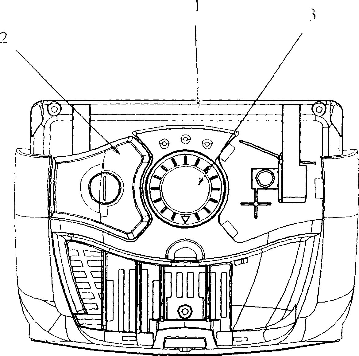
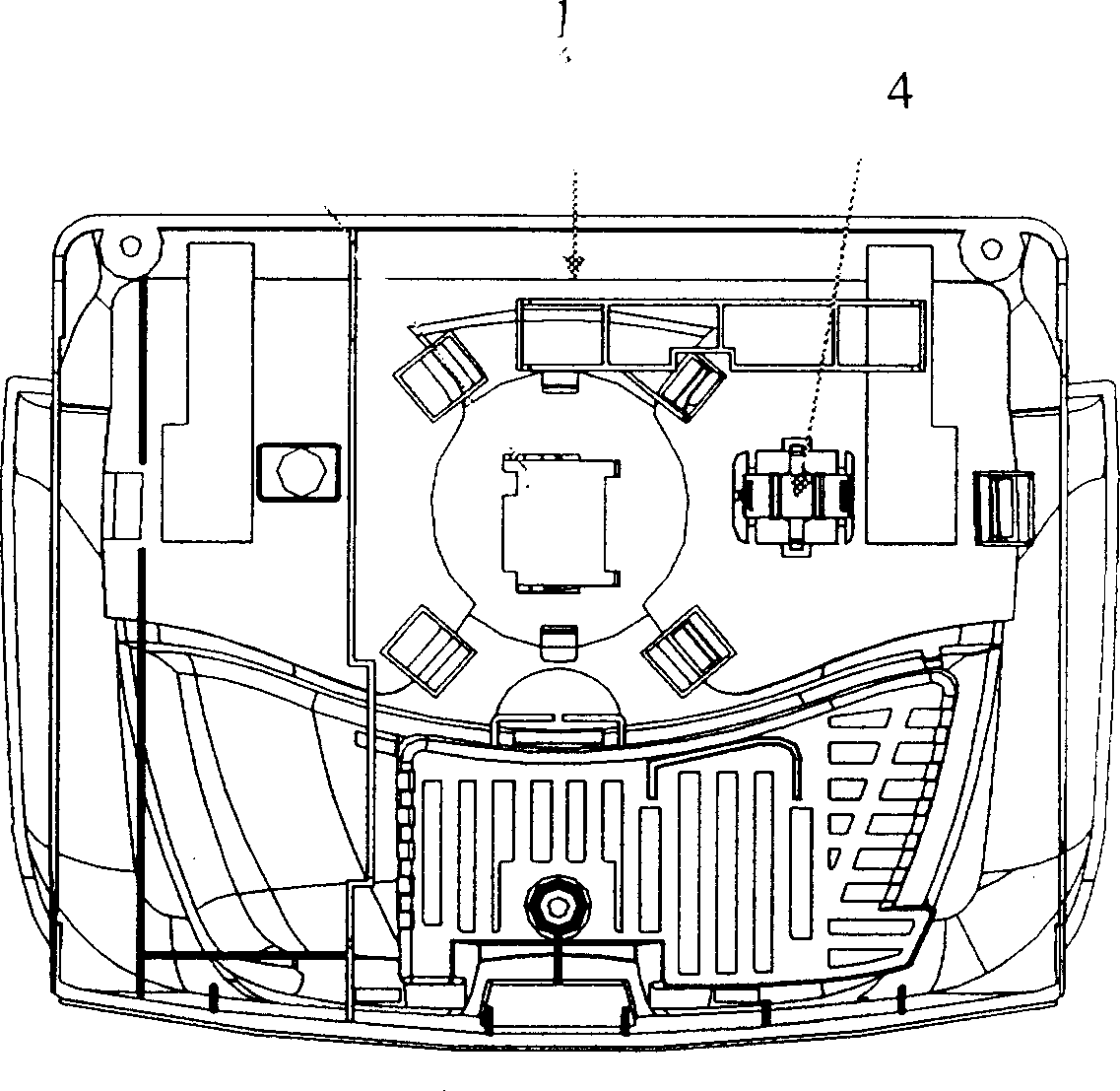
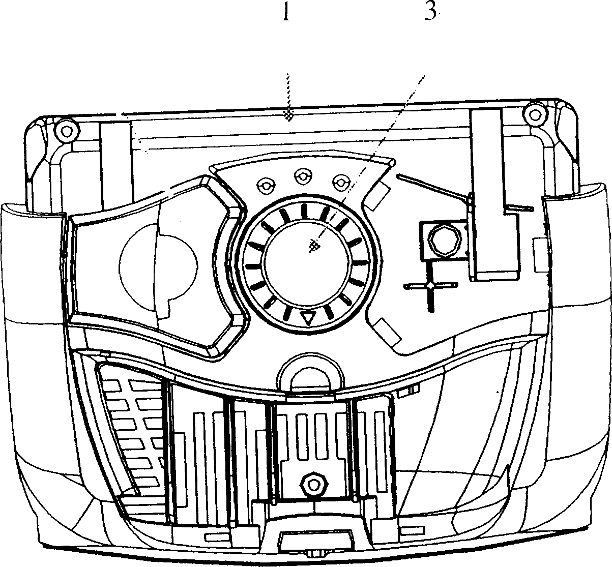
[0020] The specific embodiments of the present invention will now be described with reference to the drawings. Such as image 3 with Figure 4 As shown, the rotary switch of the vacuum cleaner according to the present invention is arranged on the upper cover 1 of the body of the vacuum cleaner, and is composed of a rotary dial 4 and a PWB (sliding varistor). The knob plate is connected to the power switch, PWB (sliding varistor) and the cable reel, and the PWB is connected to the control circuit of the fan motor.

[0021] In application, turn the knob of the knob switch, turn on the power switch, and then continue to turn the knob of the knob switch, and adjust the speed of the vacuum cleaner fan motor through the PWB to adjust the suction rate of the vacuum cleaner.


PUM


Abstract

The invention relates to a knob switch of dust-collector which is arranged on the upper cover of main body and comprised by the knob plate and the PWB (slide rheostat). Wherein, the knob plate is connected to the power switch, PWB (slide rheostat) and coil winder while the PWB is connected to the control circuit of fan motor. When using said related dust collector, rotating the knob plate of knob switch, first turning on the power switch to start the dust collector, and rotating the knob plate of knob switch to via the PWB adjust the rotate speed of fan motor of dust collector to adjust the suction rate. The inventive knob switch of dust collector has integrated the switch and suction rate regulation of dust collector, therefore, it has uniform functionality, simple operation, reduced components, simple assembly and reduced cost.

Description

Technical field [0001] The invention relates to a vacuum cleaner, in particular to a rotary switch of the vacuum cleaner. Background technique [0002] Generally speaking, a vacuum cleaner is a device that sucks in the dust and foreign matter on the ground by sucking the air near the ground to achieve the effect of cleaning the ground. The composition of the vacuum cleaner mainly includes the body, the suction head and the suction pipe. A device for generating suction force for air is arranged in the body, and the suction head has a suction port that opens downward and communicates with the body through a suction pipe. When the suction device in the body is activated, the suction port of the suction head is attached to the ground, and dust and foreign objects on the ground are sucked into the body through the suction port and suction pipe together with the air. The dust-containing air is inside the body. The dust and foreign matter are filtered and collected by the filter, and th...

Claims


Application Information

Patent Timeline
Patent Type & Authority Applications(China)
IPC IPC(8): A47L9/28H01C10/36H01C10/50
CPCY02B40/00
Inventor 周浩
Owner LG ELECTRONICS (TIANJIN) APPLIANCES CO LTD
Why Eureka
Try Eureka