
Decompression dry device and method

A decompression drying device and drying technology, applied in optics, instruments, optomechanical equipment, etc., can solve problems such as long time

Inactive Publication Date: 2006-04-12
DAINIPPON SCREEN MTG CO LTD
View PDF1 Cites 13 Cited by
  • Summary
  • Abstract
  • Description
  • Claims
  • Application Information

AI Technical Summary

Problems solved by technology

Therefore, there is a problem that it takes a long time before the photoresist dries

Method used


Image

  • Decompression dry device and method
  • Decompression dry device and method
  • Decompression dry device and method

Examples


Embodiment Construction

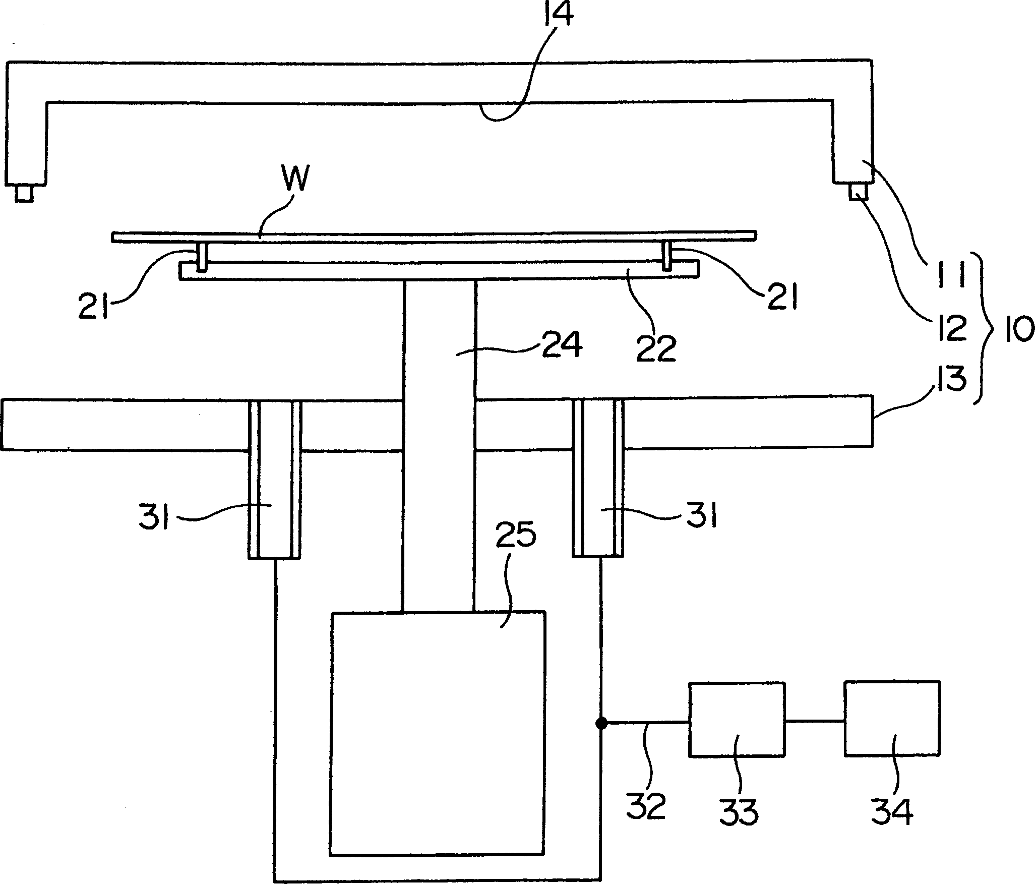
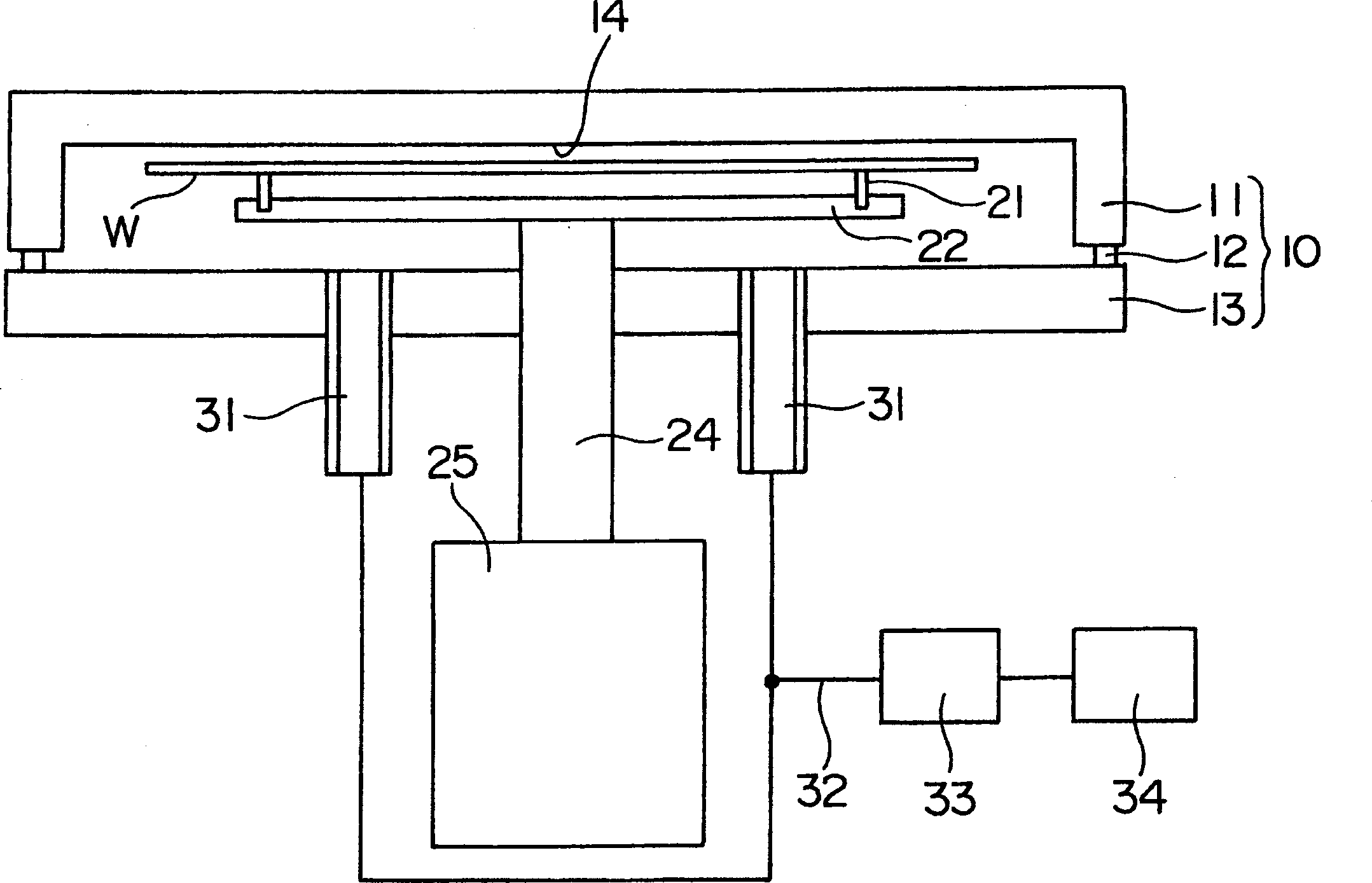
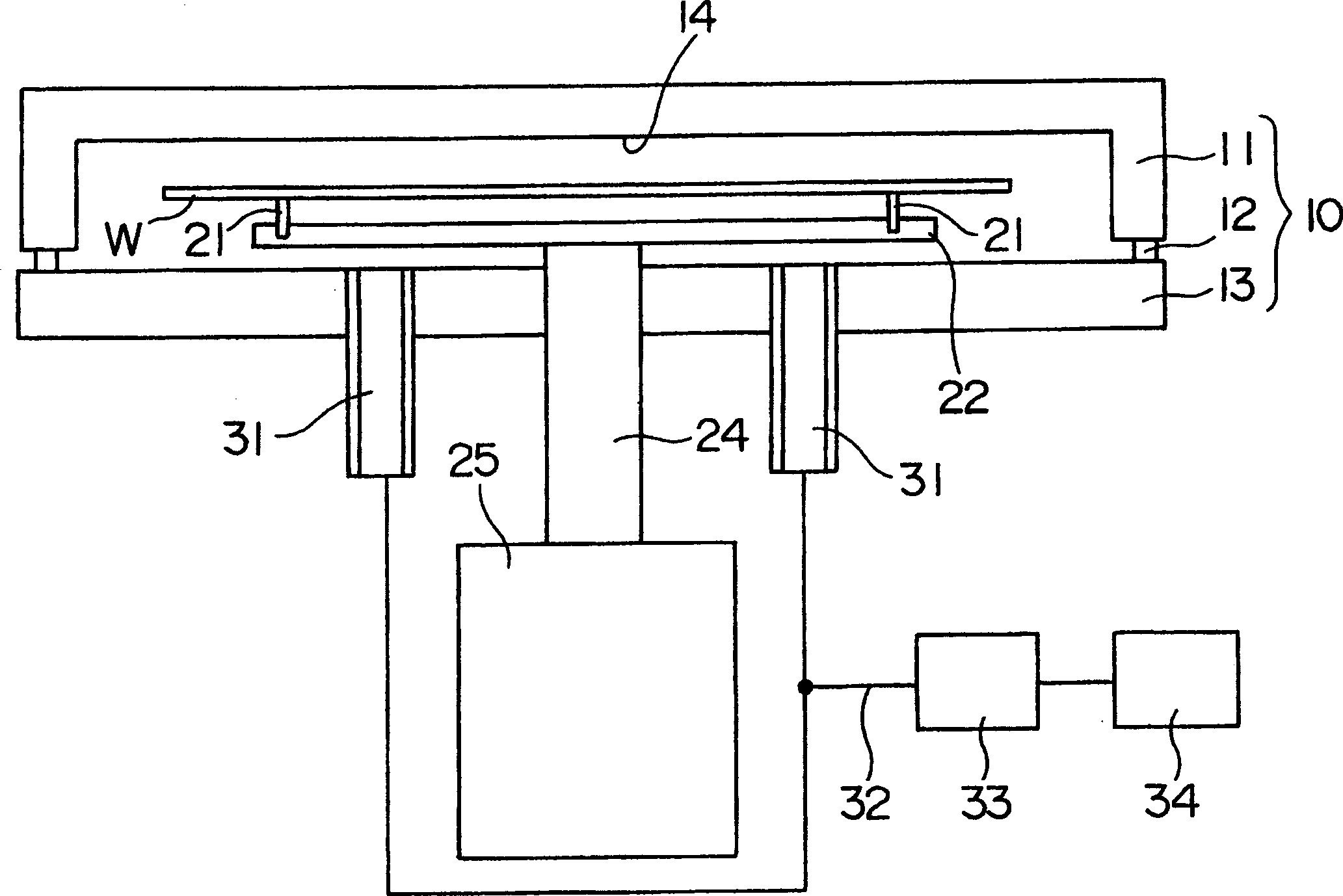
[0027] Hereinafter, embodiments of the present invention will be described based on the drawings. Figure 1 to Figure 3 It is a schematic diagram of the reduced-pressure drying apparatus concerning 1st Embodiment of this invention.

[0028] This reduced-pressure drying apparatus has a chamber 10 constituted by a lid 11 , a seal 12 , and a base 13 , and a support plate 22 on which support pins 21 for supporting a substrate W are erected. The substrate W is supported by support pins 21 in the chamber 10 in a horizontal posture with its main surface facing upward.

[0029] In the base 13 of the chamber 10, an exhaust port 31 is formed. The exhaust port 31 is connected to a vacuum pump 34 through a pipeline 32 . Furthermore, between the exhaust port 31 and the vacuum pump 34 , a damper 33 capable of controlling the amount of exhaust gas from the exhaust port 31 in two stages is arranged. In addition, an exhaust fan or the like may be used instead of the vacuum pump 34 . In add...


PUM


Abstract

To provide a vacuum dryer and a vacuum drying method capable of rapidly drying a thin film formed on a main surface of a substrate without causing bumping. A support pin 21 is raised with a support plate 22 to minimize the distance between the main surface of the substrate W and the upper surface 14 of a chamber 10, and evacuation is performed in a small displacement in this state. Therefore, the support pin 21 is lowered with the support plate 22 to increase the distance between the main surface of the substrate W and the upper surface 14 of the chamber 10, and evacuation is performed in a large displacement in this state.

Description

technical field [0001] The invention relates to a decompression drying device and a decompression drying method. Background technique [0002] JP Unexamined Publication No. 7-283108 discloses a vacuum drying device for drying under reduced pressure a thin film such as a photoresist coated on a substrate, such as a semiconductor wafer, a liquid crystal display panel, etc. A glass substrate, or a mask substrate for semiconductor manufacturing equipment, etc. are used. The reduced-pressure drying device described in JP Unexamined Publication No. 7-283108 uses a vacuum pump to depressurize the chamber in which the substrate is loaded, thereby promoting the evaporation of the solvent that is the center of the composition of the resist liquid, and makes the photoresist dry. Can dry quickly. When the photoresist is dried using such a reduced-pressure drying device, the photoresist can be dried uniformly without being affected by external factors such as wind or heat. [0003] Wh...

Claims


Application Information

Patent Timeline
Patent Type & Authority Applications(China)
IPC IPC(8): G03F7/16G03F7/00
CPCG03F7/70841G03F7/70858
Inventor 柿村崇
Owner DAINIPPON SCREEN MTG CO LTD
Learn More