Fuel filter arrangement

A technology of fuel filter and fuel oil, which is applied in the direction of membrane filter, filtration separation, charging system, etc., and can solve the problem of inability to use fuel oil, etc.

Active Publication Date: 2010-05-26
TI GRP AUTOMATED PROPULSION SYST LLC
View PDF6 Cites 0 Cited by
  • Summary
  • Abstract
  • Description
  • Claims
  • Application Information

AI Technical Summary

Problems solved by technology

In use however, the engine usually cannot utilize all the fuel supplied by the high pressure pump

Method used


Image

  • Fuel filter arrangement
  • Fuel filter arrangement
  • Fuel filter arrangement

Examples


Embodiment Construction

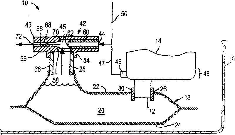
[0021] Referring to these drawings in detail, figure 1 There is shown a fuel filter assembly 10 constructed in accordance with a presently preferred embodiment of the invention, adapted to be connected to an inlet 12 of a high pressure fuel pump 14 preferably driven by an electric motor and disposed in a fuel tank 16 . The filter arrangement 10 facilitates the removal of fuel vapors from liquid fuel near the inlet 12 of the fuel pump 14 . Therefore, the fuel pump 14 can efficiently pump liquid fuel to the vehicle's engine (not shown), thereby maximizing the performance of the vehicle's engine and fuel pump.

[0022] still come to see figure 1 The filter device 10 has at least one layer of liquid fuel permeable material, hereinafter referred to as an outer layer 18 of permeable material, which forms a substantially closed cavity 20 . The outer layer 18 is preferably defined by a pair of walls, hereinafter referred to as upper wall 22 and lower wall 24 , which are sealed toget...


PUM


Abstract

A fuel filter and vapor separator arrangement having at least one layer of liquid fuel permeable material defining at least one substantially enclosed cavity. The permeable material has at least one opening to provide fluid communication of liquid fuel within the cavity with an inlet of a high pressure fuel pump outside the cavity. A jet pump and / or fuel vapor vent is arranged relative to the cavity to facilitate the elimination of fuel vapor flowing to the high pressure fuel pump.

Description

technical field [0001] This invention relates generally to fuel filters for volatile fuel systems, and more particularly to fuel filter and vapor separator arrangements for fuel pumps in fuel tanks. Background technique [0002] The fuel tank in a car usually has a high pressure fuel pump that sits inside the tank and supplies fuel to the car's engine. In use, however, the engine is often unable to utilize all the fuel supplied by the high pressure pump. Therefore, some cars are equipped with a return line to direct unused fuel back into the fuel tank for recirculation. The returned fuel is usually already heated and causes air bubbles to form when it is released into the fuel tank. The presence of air bubbles in the fuel tank is undesirable, especially if the air bubbles are sucked into the high-pressure fuel pump, which can negatively affect the efficiency of the fuel pump and the fuel flow rate delivered to the engine. [0003] Various attempts have been made to elimin...

Claims


Application Information

Patent Timeline
Patent Type & Authority Patents(China)
IPC IPC(8): F02M37/22
CPCB01D2201/208F02M37/025F02M37/10B01D35/0273F02M2037/228F04F5/10F02M37/50
Inventor D·J·卡特林B·J·格特R·B·库恩滋里G·A·莫斯J·M·罗斯E·J·塔拉斯基
Owner TI GRP AUTOMATED PROPULSION SYST LLC
Why Eureka
Try Eureka