Compressor

A technology for compressors and space compression, applied in the field of compressors, which can solve problems such as insufficient oil supply, increased high and low pressure differences, and reduced compressor performance, and achieve the effects of reducing pulsation, improving sealing, and reducing vibration

Inactive Publication Date: 2006-04-05
SANYO ELECTRIC CO LTD
View PDF1 Cites 0 Cited by
  • Summary
  • Abstract
  • Description
  • Claims
  • Application Information

AI Technical Summary

Problems solved by technology

[0005] However, in the structure of the above-mentioned document 2, since the high-pressure chamber and the low-pressure chamber are formed adjacent to the upper and lower sides of the compression member (swash plate) in the entire cylinder, there is a problem of poor efficiency caused by refrigerant leakage due to an increase in the high-pressure and low-pressure differences. question
[0006] In particular, when one side of the compression member is arranged on the side of the driving element, the refrigerant in the compression space tends to leak from between the rotating shaft and the bearing of the rotating shaft, resulting in a decrease in the performance of the compressor.
[0007] In addition, in the compressor of the above-mentioned document 2 structure, also like the current compressor of the above-mentioned document 1, an oil collecting pan is formed in the lower part of the airtight container, and oil is supplied from the oil collecting pan to the compression element through an oil pump. , For example, when the compression element is arranged on the upper side of the driving element, etc., and the compression element is installed at a position away from the oil pan, it is difficult to supply oil through the oil pump, resulting in insufficient oil supply.

Method used


Image

  • Compressor
  • Compressor
  • Compressor

Examples


Embodiment 1

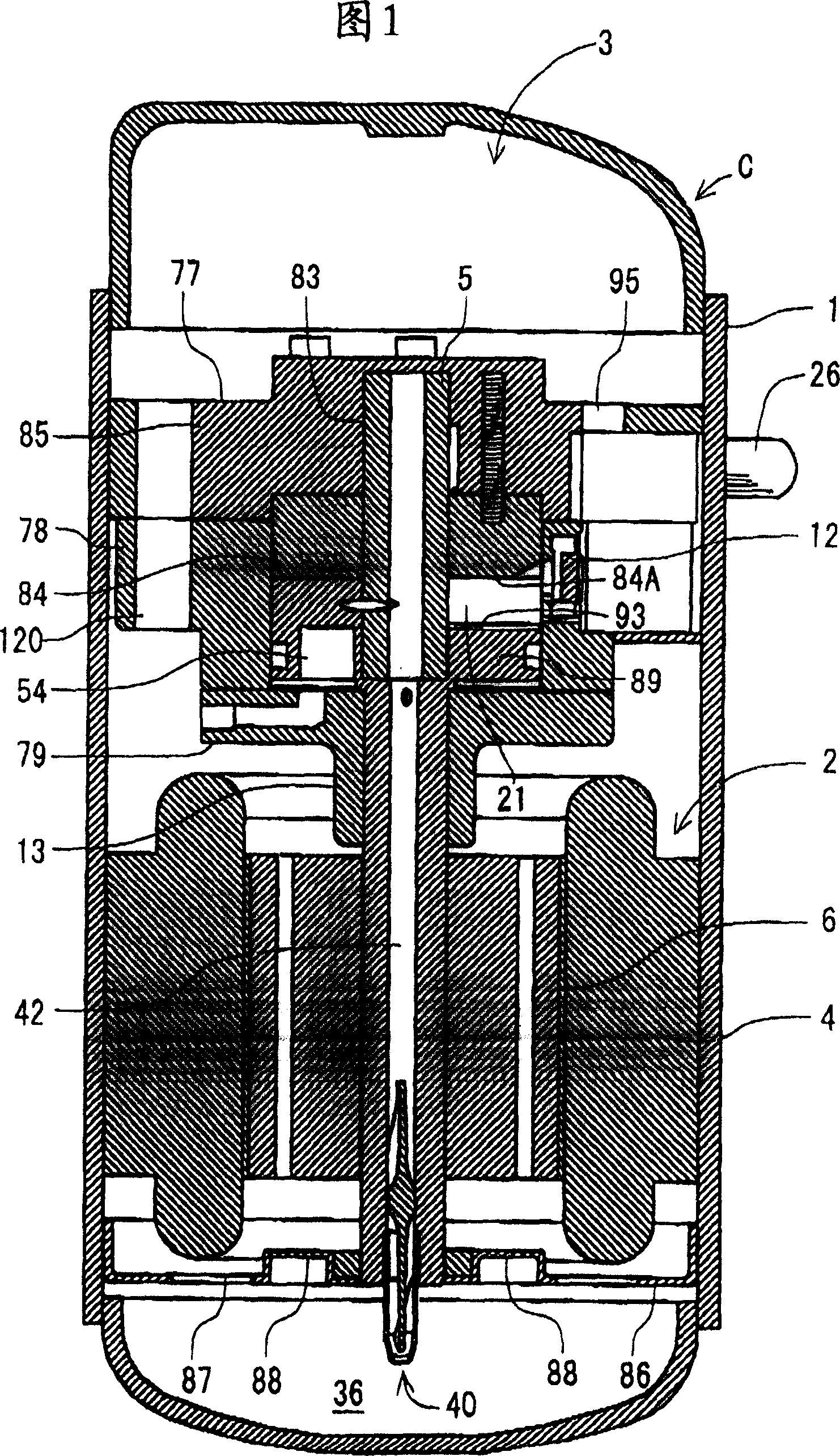
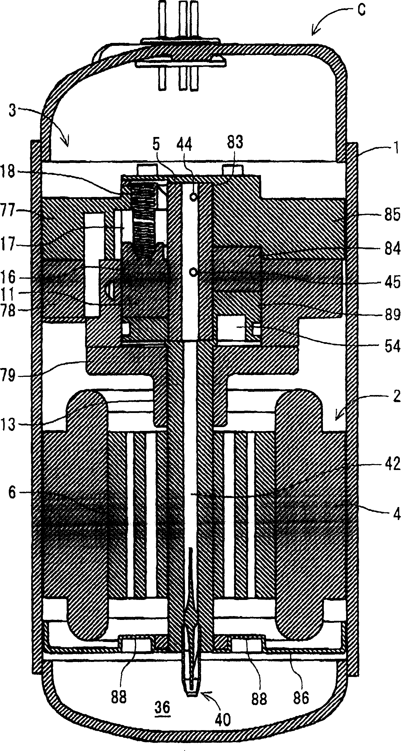
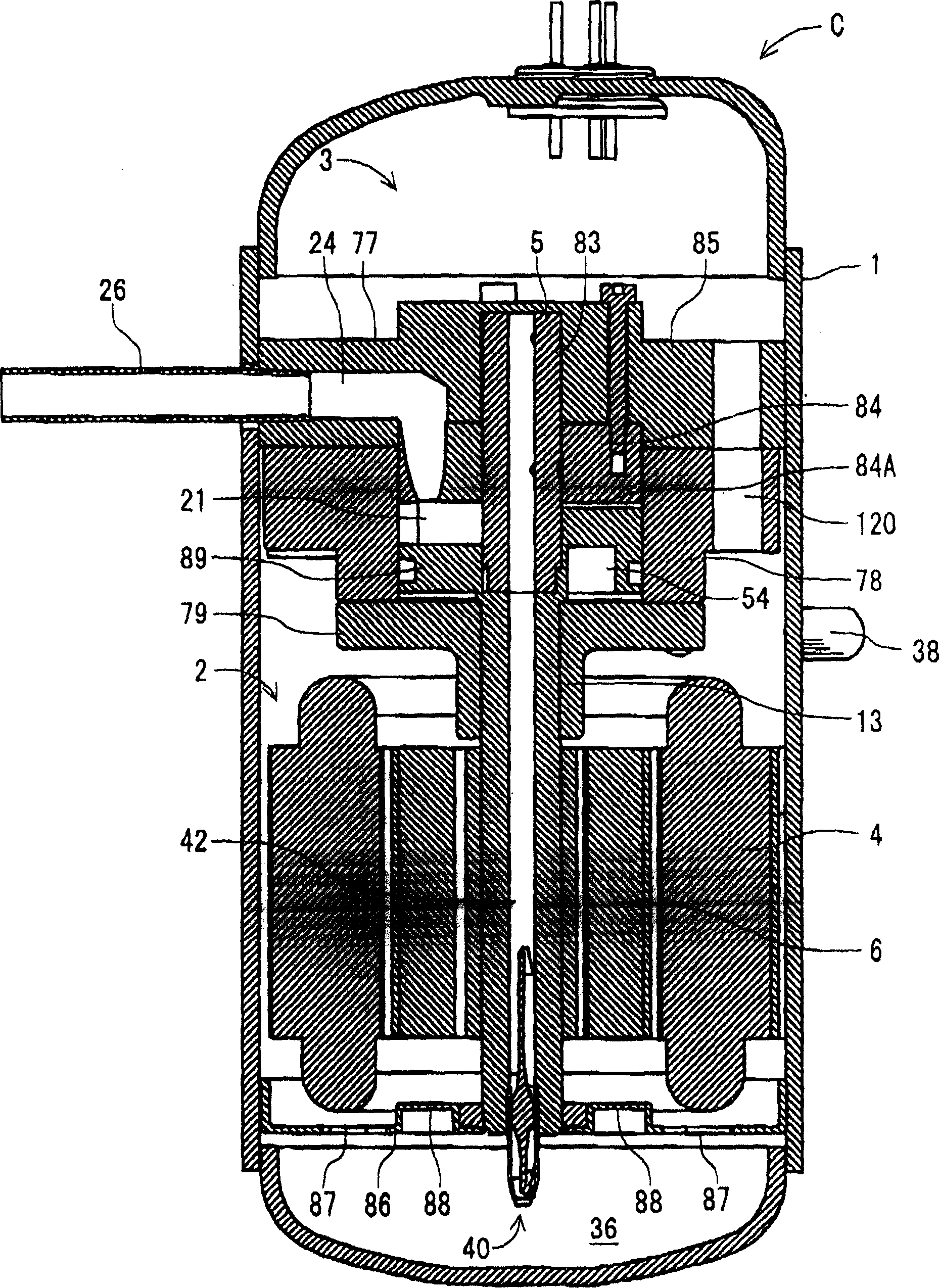
[0039] Fig. 1 shows a longitudinal sectional side view of a compressor C according to a first embodiment of the present invention, figure 2 Another longitudinal sectional side view showing the compressor C of Fig. 1, image 3 Another longitudinal sectional side view showing the compressor C of FIG. 1, Figure 4 A perspective view showing a compression element 3 of the compressor 1 in FIG. 1 .

[0040] In each figure, 1 is an airtight container, and in this airtight container 1, the compression element 3 is accommodated in the upper side, and the drive element 2 is accommodated in the lower side, respectively. That is, the compression element 3 is arranged above the driving element 2 .

[0041] The driving element 2 is a motor, and includes: a stator 4 fixed to the inner wall of the airtight container 1 and wound with a stator coil; and a rotor 6 having a rotating shaft 5 inside and at the center of the stator 4 .

[0042] The compression element 3 has: a support member 77 f...

Embodiment 2

[0073] Below, refer to Figure 5 ~ Figure 7 A second embodiment of the present invention will be described. Figure 5 ~ Figure 7 It is a vertical side view of such a compressor C, and each figure shows a different cross section. In addition, in Figure 5 ~ Figure 7 In the above figure 1~ Figure 4 Components shown with the same numbers exert the same or similar effects, and therefore explanations are omitted.

[0074] In this embodiment, the drive element 2 is accommodated on the upper side and the compression element 3 is accommodated on the lower side in the container 1 . That is, the compression element 3 is arranged below the drive element 2 .

[0075] The compression element 3 is composed of a main support member 107 fixed to the inner wall of the airtight container 1, a cylinder 108 mounted on the lower side of the main support member 107 with bolts, a compression member 109 arranged in the cylinder 108, a vane 11, and a discharge valve 12. It is composed of a sub-s...

Embodiment 3

[0099] the following, Figure 8 ~ Figure 10 represents a compressor C of a third embodiment of the present invention, Figure 8 ~ Figure 10 It is a vertical side view of the compressor C of the third embodiment, and each figure shows a different cross section. In addition, in Figure 8 ~ Figure 10 Attached to the above Figure 1 ~ Figure 7 Components shown with the same numbers have the same or similar effects, and therefore explanations are omitted.

[0100] At this time, the drive element 2 is accommodated on the lower side and the compression element 3 is accommodated on the upper side in the airtight container 1, and the compression space 21 of the compression element 3 is used as the lower surface side of the drive element 2 side of the compression member 109, and the lower surface of the compression member 109 is (One surface) 113 is formed in the shape which inclines continuously from top dead center to bottom dead center.

[0101] In addition, a slit 16 is formed i...


PUM


Abstract

The invention provides a compressor, which has the function of improving the cooling medium leakage and realize the performance of the compressor to be increased. The compressor has a driving factor contained in a sealed container of the compressor and a compression factor driven by a rotating shaft of the driving factor. The compression factor has a cylinder, a suction port, an exhaust port, a compression component and blades; wherein, the cylinder forms a compression space in the interior, the suction port and the exhaust port are communicated with the compression space of the cylinder, the compression component and an surface which is axially crossed with the rotating shaft are slant between an upper dead center and a lower dead center in a continuous way, at the same time, the compression component is arranged in the cylinder and is driven by the rotating shaft to rotate, liquid (cooling medium) sucked in from the suction port is compressed and discharged from the exhaust port, and the blades which divide the compression space in the cylinder into a low pressure chamber and a high pressure chamber are arranged between the suction port and the exhaust port, and are contacted with the top of one surface of the compression component. The compressor arranges one surface of the compression component at the opposite side of the driving factor.

Description

technical field [0001] The present invention relates to a compressor for compressing and discharging fluids such as refrigerant and air. Background technique [0002] Conventionally, for example, in refrigerators, a method in which a compressor compresses a refrigerant and circulates the refrigerant in a circuit is used. Examples of such compressors include a rotary compressor called a rotary compressor (see, for example, JP-A-5-99172, Document 1), a scroll compressor, and a screw compressor. [0003] The above-mentioned rotary compressor has the advantages of relatively simple structure and low manufacturing cost, but has the problems of large vibration and torque fluctuation. In addition, scroll compressors and screw compressors have problems of difficulty in processing and high cost, although torque fluctuations are small. [0004] Therefore, it has also been developed to install a swash plate as a rotating compression part in the cylinder, and use a vane (vane) to divi...

Claims


Application Information

Patent Timeline
Patent Type & Authority Applications(China)
IPC IPC(8): F04C18/00
Inventor 小笠原弘丞西川刚弘须田章博原正之
Owner SANYO ELECTRIC CO LTD
Why Eureka
Try Eureka