
Hydraulic vane change device for wind-driven generator

A wind turbine and hydraulic technology, which is applied to wind turbines, wind turbine control, wind power generation and other directions, can solve the problems of complex structure, difficult maintenance and slow response of variable-pitch fans, and achieves simple structure, convenient maintenance and low cost. Effect

Inactive Publication Date: 2006-03-29
朱汪逸
View PDF0 Cites 13 Cited by
  • Summary
  • Abstract
  • Description
  • Claims
  • Application Information

AI Technical Summary

Problems solved by technology

[0004] The existing variable pitch fan has complex structure, high cost and difficult maintenance
Moreover, the action of the servo motor control system takes a certain amount of time, and the response is slow when the wind force changes complicatedly.

Method used


Image

  • Hydraulic vane change device for wind-driven generator
  • Hydraulic vane change device for wind-driven generator

Examples


Embodiment Construction

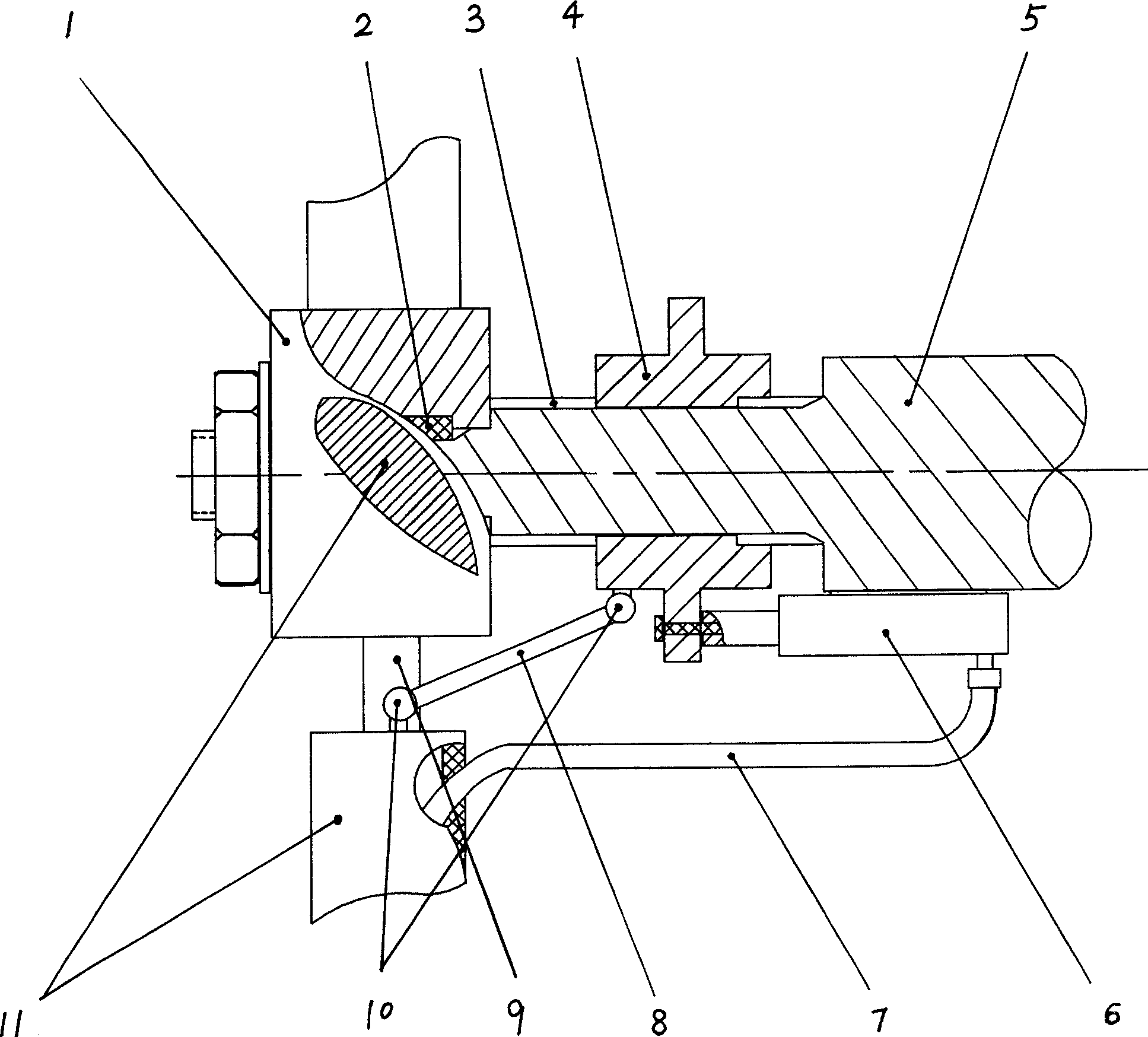
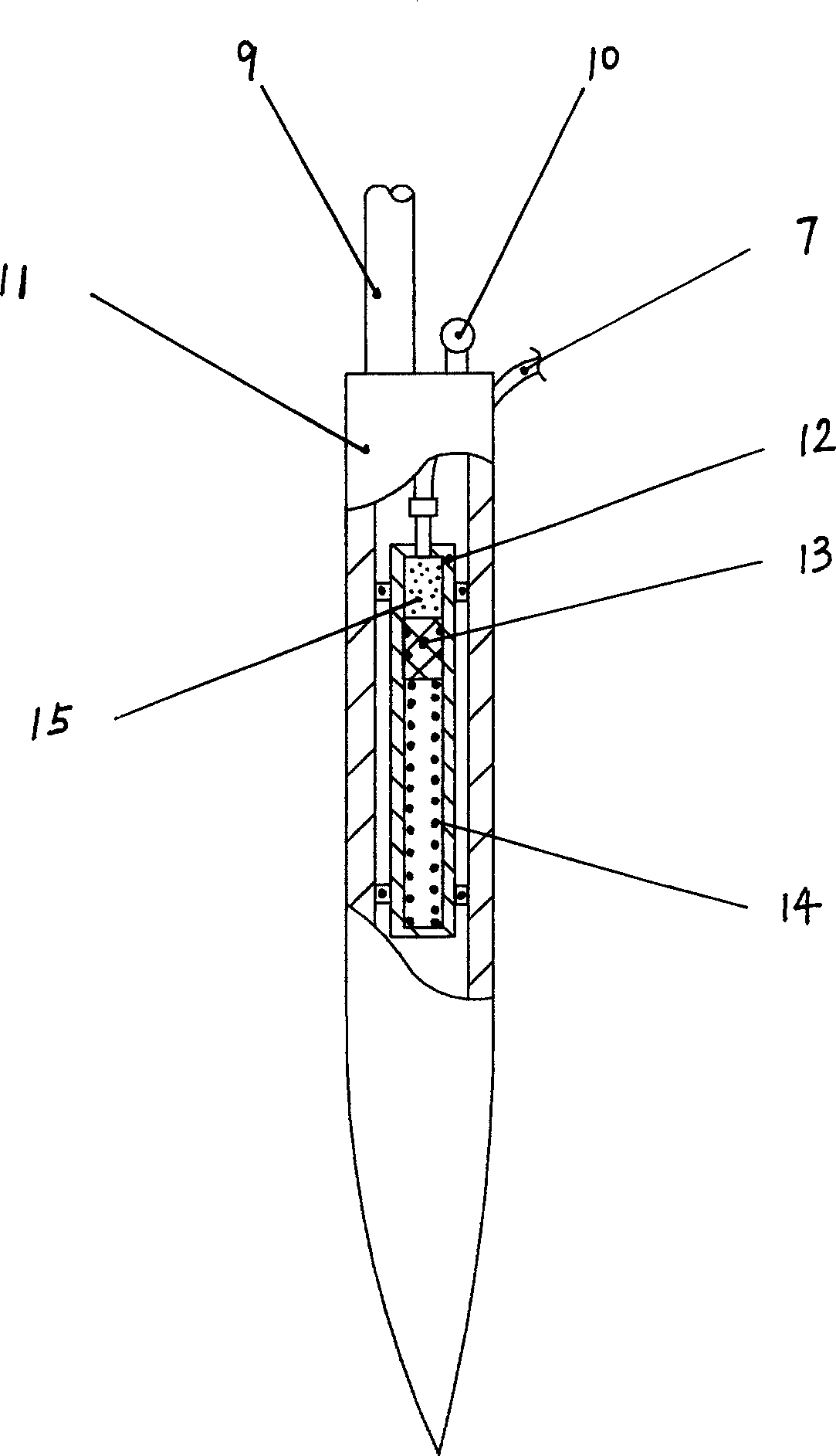
[0015] See figure 1 In the embodiment of the wind turbine hydraulic pitch device, the hub 1 is fixedly installed on the main shaft, and the hub 1 is provided with three propeller shafts 9 that are perpendicular to the main shaft and can rotate, and the blades 11 are installed one by one on each corresponding On the propeller shaft 9, the main shaft 5 is provided with a sliding sleeve 4, which is movably connected by a spline. The sliding sleeve 4 can slide along the axial direction of the main shaft 5, and the blade 11 is on the side of the propeller shaft 9 and on the sliding sleeve 4. The corresponding position is provided with a connecting head 10, the connecting heads 10 are connected by a connecting rod 8. The main shaft 5 is equipped with a hydraulic cylinder 6 with the same number of blades, the plunger of the hydraulic cylinder 6 is connected to the sliding sleeve 4, and the blade 11 A pressure storage tank is arranged inside, and the pressure storage tank is connected wi...


PUM


Abstract

In the invention, at least two rotary paddle shafts perpendicular to the main shaft is set on the propeller hub fixed on the main shaft. The paddle is mounted on the paddle shaft one by one. A slide-sleeve is disposed on the main shaft. The connecting heads are disposed beside of the paddle shafts on the paddles and on the slide-sleeve. Between the connecting heads are connected by the connecting-rods. The hydraulic cylinders with the same numbers as the paddles are mounted on the main shaft. The plunger of the hydraulic cylinder is connected on the slide-sleeve. The pressure liquid-storage tank is disposed in the paddle. The pressure liquid-storage tank is connected with the hydraulic cylinder via the pipeline.

Description

Technical field [0001] The present invention relates to wind power generation equipment, in particular to the improvement of a pitching device of a wind power generator. Background technique [0002] There are two types of large-scale wind turbines: fixed propeller and variable propeller. The fixed blade means that the angle of attack of the blades is fixed. When the wind power is greater than a certain value, the speed will be too high and the unit cannot work normally; the blade angle of attack of the variable pitch fan can be adjusted. When the wind is small, the angle of attack is large, and the wind conversion efficiency High, when the wind is strong, the angle of attack becomes smaller, reducing the conversion efficiency of the wind, so that the wind turbine can work normally under various wind conditions. [0003] The structure of the blade wheel of the pitch fan is that the hub is fixedly installed on the main shaft, and at least two shafts that can rotate perpendicular t...

Claims


Application Information

Patent Timeline
Patent Type & Authority Applications(China)
IPC IPC(8): F03D7/04
CPCY02E10/723Y02E10/72
Inventor 朱汪逸
Owner 朱汪逸
Learn More