
Electronic weighing system for loading machine and method for metering loading capacity

A weighing system and loader technology, applied in loading/unloading, weighing, special scales, etc., can solve the problems of low measurement accuracy and poor reliability, and achieve scientific measurement methods, convenient use and maintenance, and convenient operation. Effect

Inactive Publication Date: 2006-03-22
中国铁路南宁局集团有限公司科学技术研究所 +1
View PDF0 Cites 27 Cited by
  • Summary
  • Abstract
  • Description
  • Claims
  • Application Information

AI Technical Summary

Problems solved by technology

[0003] The technical problem to be solved by the present invention is that the measurement accuracy and reliability of the existing loader electronic scales that use hydraulic sensing methods for measurement are not high, and the problem of poor reliability is provided. Loader Electronic Weighing System with Higher Weighing Accuracy in Dynamic Environment and Method for Measuring Loading Capacity Using It

Method used


Image

  • Electronic weighing system for loading machine and method for metering loading capacity
  • Electronic weighing system for loading machine and method for metering loading capacity
  • Electronic weighing system for loading machine and method for metering loading capacity

Examples


Embodiment 1

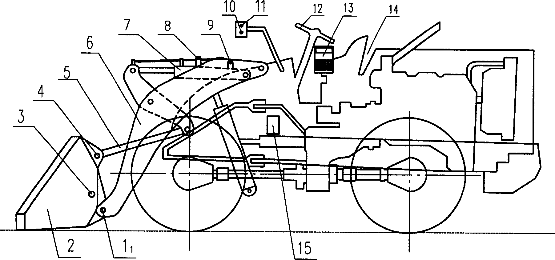
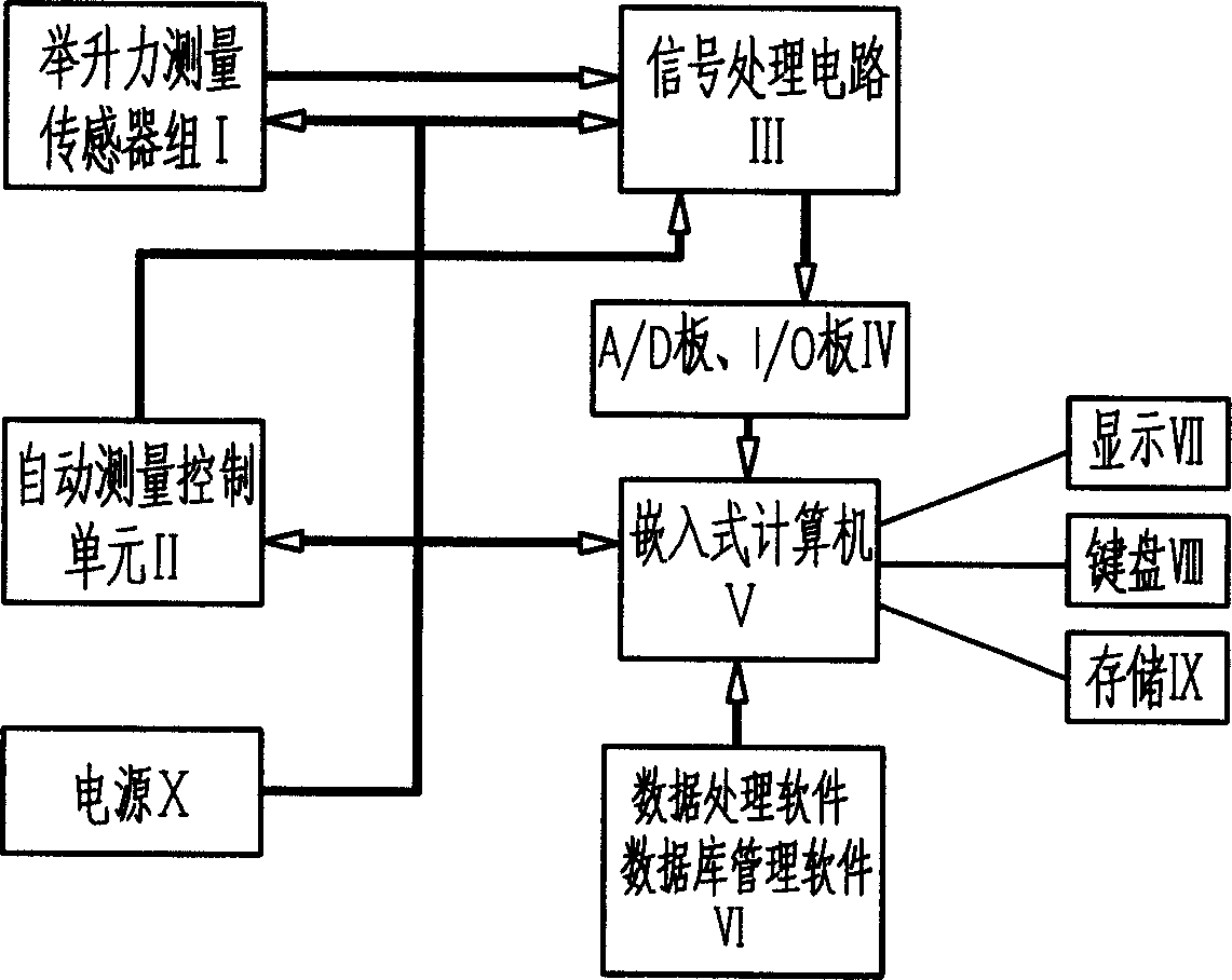
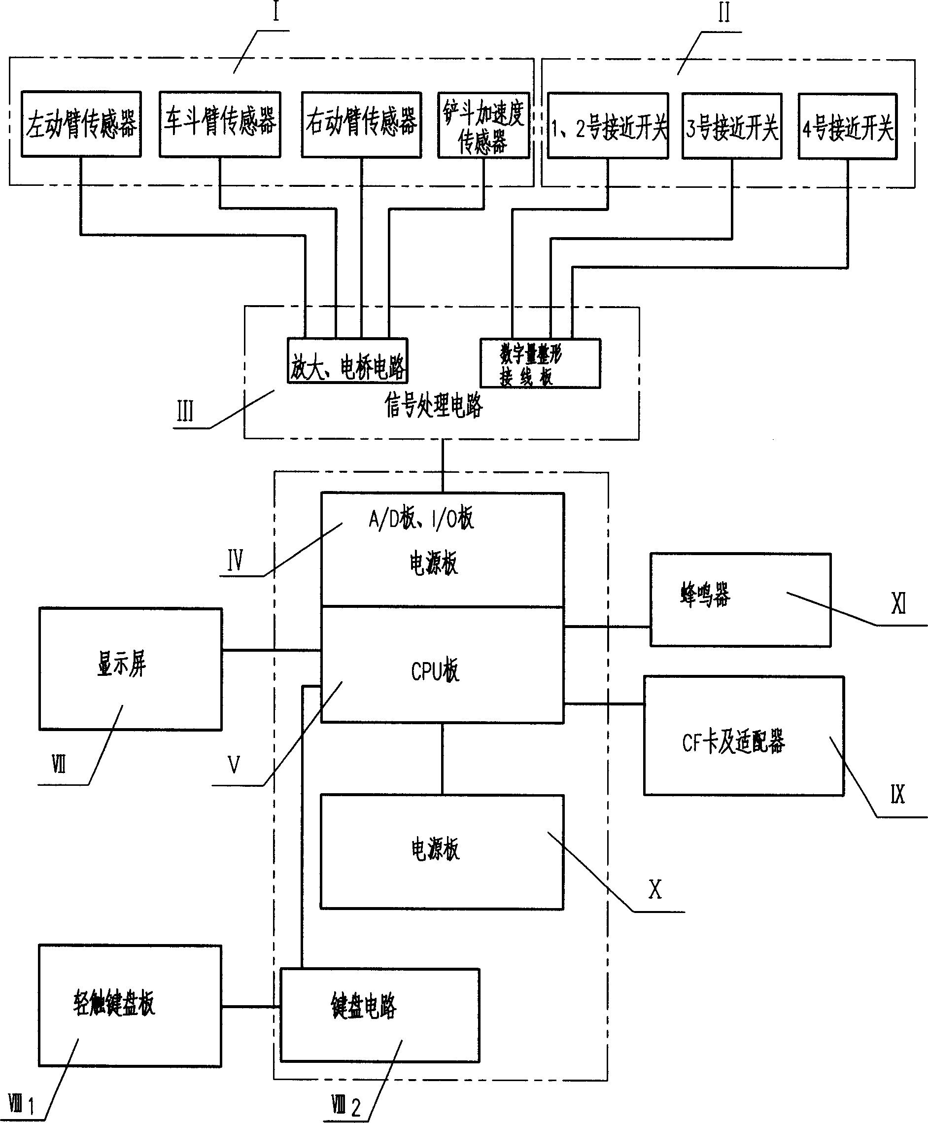
[0041]A loader electronic scale weighing system. The system includes a sensor group, an automatic measurement control unit, a signal processing circuit, a computer and a processing system, and a power supply X. The sensor group is the lifting force measurement sensor group I, and the automatic measurement control unit II is a bucket position measurement switch. group, the computer and processing system is an embedded computer V with weighing software and loading quality information management system software VI, the lifting force measurement sensor group I consists of pins installed at the junction of the bucket 2 and the left and right lifting arms The left and right lifting arm sensors 11, 12 on the shaft (not shown in the figure 12), the bucket acceleration sensor 3 installed on any position of the loader bucket 2, installed on the pin shaft at the junction of the bucket and the turning arm The flip arm sensor 4 is composed of the flip arm sensor 4. The automatic measuremen...

Embodiment 2

[0044] The method of measuring the load capacity of the loader by using the loader electronic weighing system described in Embodiment 1, the method measures the quality of the material in the bucket by measuring the lifting force of the loader bucket, that is: between the bucket 2 and Install the left and right lift arm sensor 1 on the pin shaft at the junction of the left and right lift arms 1 ,1 2 , the bucket acceleration sensor 3 is installed on the loader bucket 2, and the turning arm sensor 4 is installed on the pin shaft at the junction of the bucket and the turning arm to form the lifting force measurement sensor group I, and its data is input into the signal processing circuit III, and the signal The signal amplified and filtered by the processing circuit III is input to the embedded computer V through A / D data conversion, and then the weight of the material scooped by the loader bucket is calculated by the computer according to the relationship between the lifting fo...


PUM


Abstract

The electronic weighing system includes sensors, automatic measuring and controlling unit, signal processing circuit, computer and processing system, and power source. The lifting force measuring sensors and the bucket position measuring switches as the automatic measuring and controlling unit have outputs connected to the inputs of the signal processing circuit, and the signal processing circuit has output connected via A / D converting module and I / O port to the embedded computer with weighing software. The loaded amount measuring method is to measure the lifting force of the bucket with the said system to measure the mass of the material inside the bucket, and includes the steps of power-on system test, inputting relevant information, reset, automatic weighing, accumulating, reset, re-weighing, etc. The present invention has relatively high weighing accuracy.

Description

technical field [0001] The invention relates to a weighing system of a loader, in particular to an electronic weighing system of a loader and a method for measuring the loading capacity of the loader by using the system. Background technique [0002] Loader electronic scales at home and abroad are all measured by hydraulic transmission. For example, the patent application No. 9410411.X "Measurement method and device for loader load capacity" is one of them. On the oil inlet pipeline of the boom cylinder of the loader bucket, the pressure sensor used to measure the liquid pressure measures the sensing signal of the mass loaded on the bucket, and the above sensing signal is received by the measurement display device, converted and displayed. ", this measurement method will not be popularized in batches due to low measurement accuracy and poor reliability due to oil temperature, internal friction, pollution, seal wear and dynamic factors of weighing during travel. Contents of...

Claims


Application Information

Patent Timeline
Patent Type & Authority Applications(China)
IPC IPC(8): G01G19/08B65G65/00
Inventor 徐海贤蒋漪泉杜占江吴任天
Owner 中国铁路南宁局集团有限公司科学技术研究所
Learn More