Scroll compressor
A scroll compressor and compression chamber technology, applied in the field of scroll compressors, can solve the problems of increased cost, difficulty in ensuring the sealing performance of coils, and increased number of production steps
- Summary
- Abstract
- Description
- Claims
- Application Information
AI Technical Summary
Problems solved by technology
Method used
Image


Examples
no. 1 approach
[0038] Embodiments of the present invention will be described below with reference to these drawings. The present invention is not limited to these embodiments.
[0039] figure 1It is a cross-sectional view of the scroll compressor according to the first embodiment of the present invention. The orbiting scroll 13 engaged with the fixed scroll 12 is sandwiched between the main bearing member 11 of the crankshaft 4 fixed in the container 1 by welding or shrink fitting and the fixed scroll 12 bolted to the main bearing member 11 , thereby constituting a scroll compressor mechanism 2 . A limited rotation mechanism 14 , such as an Oldham ring, is provided between the orbiting wrap 13 and the main bearing member 11 . The restricting rotation mechanism 14 guides the orbiting scroll 13 so as to prevent the rotation of the orbiting scroll 13 and allow it to move along a circular orbit. The orbiting scroll 13 is eccentrically driven by the main shaft portion 4a on the upper end of ...
no. 2 approach
[0049] Figure 4 It is a graph showing the variation of the volume of the compression chamber with respect to the rotation angle when the involute angle θa of the scroll compressor according to the second embodiment of the present invention is varied within the range of θb Figure 4 It shows that when the involute angle θa at the end of the inner wall curve of the scroll wrap 12b of the fixed scroll 12 and the involute angle θb at the end of the inner wall curve of the scroll wrap 13b of the spiral scroll 13 are θb<θa<θb When changing within the range of +π, the volume of the compression chamber 15 changes with respect to the rotation angle (rotation angle) of the crankshaft 4 .
[0050] Here, a coordinate system is provided in which the center of the base circle of the inner wall curve of the scroll wrap 12b of the fixed scroll 12 is defined as the origin, and an arbitrary direction is defined as the involute angle: θ=0. The direction of turning counterclockwise from the front...
no. 3 approach
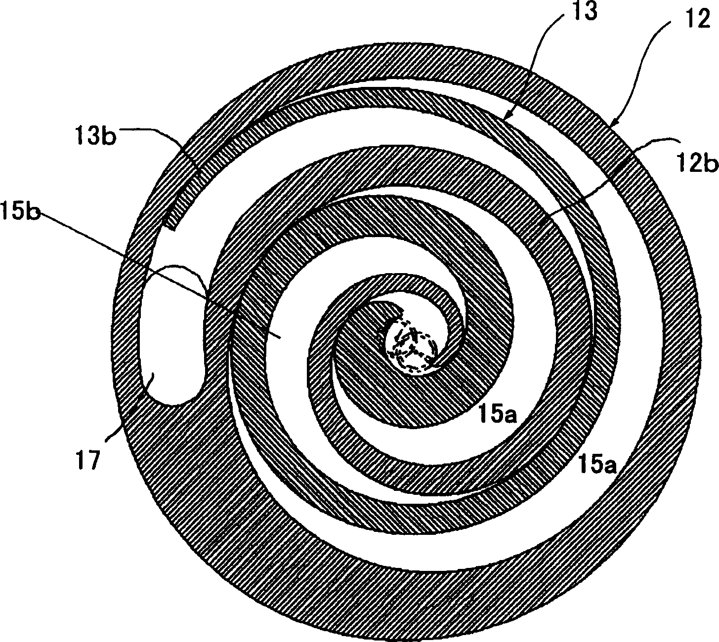
[0053] Figure 5 is a plan view showing the wrap shape of a scroll compressor according to a third embodiment of the present invention. exist Figure 5 , the center position of the base circle radius a and the center position of the base circle radius b are separated from each other. Thus, the compression chamber 15b formed on the inner wall side of the wrap wrap 13b of the orbiting scroll 13 is compressed faster than the compression chamber 15a formed on the outer wall side of the compression wrap 13b of the orbiting scroll 13, and While maintaining this characteristic, the thickness of the scroll wrap can be varied. Therefore, the strength of the scroll wrap can be adjusted freely.
PUM
 Abstract
Description
Claims
Application Information
 - R&D
- Intellectual Property
- Life Sciences
- Materials
- Tech Scout
- Unparalleled Data Quality
- Higher Quality Content
- 60% Fewer Hallucinations
Browse by: Latest US Patents, China's latest patents, Technical Efficacy Thesaurus, Application Domain, Technology Topic, Popular Technical Reports.
© 2025 PatSnap. All rights reserved.Legal|Privacy policy|Modern Slavery Act Transparency Statement|Sitemap|About US| Contact US: help@patsnap.com