Ultrasonic sensor
An ultrasonic and sensor technology, applied in the field of ultrasonic sensors, to achieve the effect of improving the receiving sensitivity and preventing the receiving sensitivity
- Summary
- Abstract
- Description
- Claims
- Application Information
AI Technical Summary
Problems solved by technology
Method used
Image

Examples
Embodiment 1
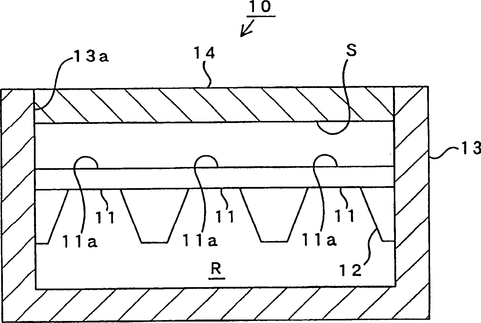
[0135] figure 1 is a side sectional view showing the receiving portion 10 in the ultrasonic sensor M according to Embodiment 1.
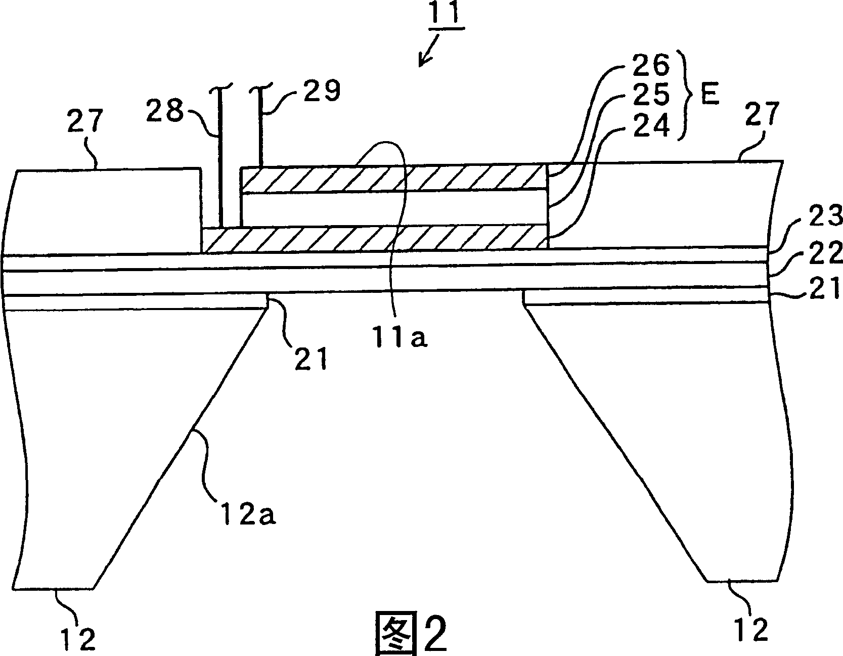
[0136] The receiving section 10 includes a plurality of piezoelectric receiving elements 11 arranged in an array. exist figure 1 In the example shown, three receiving elements 11 are shown in side sectional view.
[0137] Each receiving element 11 is formed on a single-crystal silicon substrate (single-crystal silicon chip) 12 having an SOI structure.
[0138] The substrate 12 is accommodated in a case member (accommodating member) 13 having a rectangular parallelepiped box shape with an upper open end. Also, the outer peripheral end of the substrate 12 is connected and fixed to the inner wall of the housing member 13 by an appropriate method (such as thermal welding, ultrasonic welding, bonding with an adhesive, etc.), thereby hermetically sealing the outer peripheral end of the substrate 12. The connecting part between the part and the housing...
Embodiment 2
[0194] Figure 4 is a side sectional view showing the receiving portion 40 in the ultrasonic sensor M according to Embodiment 2. FIG.
[0195] The receiving portion 40 according to Embodiment 2 differs from the receiving portion 10 of Embodiment 1 only in that the protective film 14 is replaced by a thin plate-shaped protective member 41 which is attached and fixed to each on the surface 11a of a receiving element 11.
[0196] In particular, within said receiving portion 40 a protective element 41 is connected to the front side of each receiving element 11 . A gap K is provided between the protective elements 41 of the respective receiving element 11 . For each receiving element 11 , said gap K separates the respective protective element 41 .
[0197] By replacing the receiver 40 according to Embodiment 1 such as image 3 The structure of the ultrasonic sensor M according to the second embodiment is obtained by using the receiving part 10 in the ultrasonic sensor M shown. ...
Embodiment 3
[0212] Figure 5 is a side sectional view showing the receiving portion 50 in the ultrasonic sensor M according to Embodiment 3. FIG.
[0213] The receiving portion 50 according to Embodiment 3 differs from the receiving portion 10 according to Embodiment 1 only in that a spacer member 51 and a spacer groove 52 are provided.
[0214] The lower end portion of each spacer element 51 is embedded in a corresponding spacer groove 52 formed in said base plate 12 between the respective receiving elements 11 . On the other hand, for each receiving element, the upper end portion of each spacer element 51 separates the space S from the protective film 14 .
[0215] In particular, in Figure 5 In the example shown, the lower end portion of each spacer element 51 is embedded in a corresponding spacer groove 52 formed in the base plate 12 between the three receiving elements 11A to 11C. As a result, the receiving elements 11A to 11C are separated from each other by the respective separa...
PUM
 Abstract
Description
Claims
Application Information
 - R&D
- Intellectual Property
- Life Sciences
- Materials
- Tech Scout
- Unparalleled Data Quality
- Higher Quality Content
- 60% Fewer Hallucinations
Browse by: Latest US Patents, China's latest patents, Technical Efficacy Thesaurus, Application Domain, Technology Topic, Popular Technical Reports.
© 2025 PatSnap. All rights reserved.Legal|Privacy policy|Modern Slavery Act Transparency Statement|Sitemap|About US| Contact US: help@patsnap.com