Manufacturing method of fuel cell separator, and fuel cell
A technology for fuel cells and production methods, which is applied to components of fuel cells, fuel cells, solid electrolyte fuel cells, etc., can solve problems such as reduced dimensional accuracy and reduced air tightness of bipolar plates.
- Summary
- Abstract
- Description
- Claims
- Application Information
AI Technical Summary
Problems solved by technology
Method used
Image
Examples
preparation example Construction
[0078] The nonwoven fabric holding the conductive powder used in the present invention can be produced by a known method of producing a nonwoven fabric such as a wet method or a dry method. A specific example of the production method will be described below.
[0079] (i) An example illustrated is the use of a wet process to produce the nonwoven fabric used in the present invention
[0080] A slurry is prepared by mixing thermoplastic resin fibers and conductive powder and dispersing them in water. During the preparation of the slurry, thermoplastic resin fibers are entangled in water to form entanglements (fibrous webs) within which the conductive powder particles are held. At this time, surfactants and thickeners can be added appropriately to stabilize the slurry.
[0081] The slurry is then poured on a metal screen where the fibers and powder are evenly collected. Next, the collected material is dehydrated with a dehydration roller, a heating drier and / or a vacuum dehydra...
Embodiment 1
[0140] 80 parts by weight of synthetic graphite (irregular shape, average particle size 88 μm) as conductive powder and 20 parts by weight of polyphenylene sulfide resin staple fiber (1 μm in diameter; 1 mm in length) as thermoplastic resin fibers were placed in air While mixing in a mixer, the thermoplastic resin fibers are fibrillated. The resulting mixture was fed to a nozzle having a small orifice of circular ring diameter while spraying compressed air from the compressed air inlet just upstream of the nozzle. The mixture is passed through a deflector located in front of the nozzle, thereby fibrillating the thermoplastic resin fibers and dispersing the conductive powder. The thermoplastic resin fibers and conductive powder are then collected to form a fiber web containing conductive powder. The web was passed through a pressure roll heated to 300° C., which is higher than the melting temperature of the resin (280° C.), to obtain a nonwoven fabric having a thickness of 0.2...
Embodiment 2
[0143] In addition to using 70 parts by weight of synthetic graphite (irregular shape, average particle size of 88 μm) as conductive powder and 30 parts by weight of polyphenylene sulfide resin staple fiber (1 μm in diameter; 1 mm in length) as thermoplastic resin fibers, A nonwoven fabric was obtained with the same method and conditions as in Example 1.
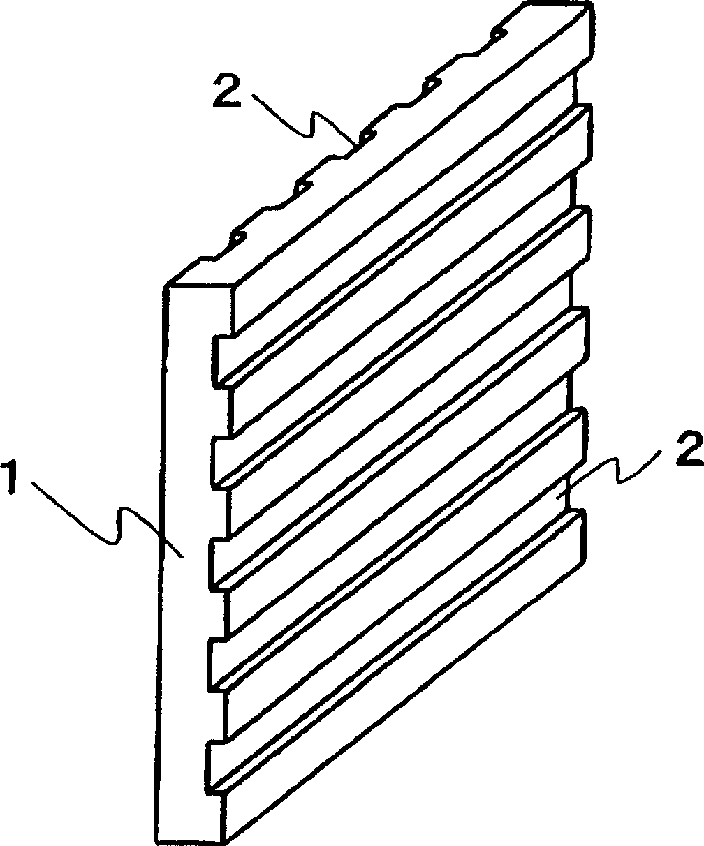
[0144] The non-woven fabric is cut into 30 sheets with a given size (250×250mm) consistent with the shape of the bipolar plate, and these 30 sheets are stacked and heated to 300°C in a furnace to melt the polyphenylene sulfide resin . The nonwoven fabric in a molten state was then quickly fed into a mold loaded in a compression molding machine and heated to 150° C., molded under a pressure of 60 MPa, and then cooled and solidified. This produced a rib molding having a width of 25 cm, a thickness of 2 mm, and a length of 25 cm in the shape shown in FIG. 4 . The molding cycle was 30 seconds.
[0145] A flat-plate-shaped mol...
PUM
| Property | Measurement | Unit |
|---|---|---|
| diameter | aaaaa | aaaaa |
| electrical resistivity | aaaaa | aaaaa |
| thickness | aaaaa | aaaaa |
Abstract
Description
Claims
Application Information
 - R&D Engineer
- R&D Manager
- IP Professional
- Industry Leading Data Capabilities
- Powerful AI technology
- Patent DNA Extraction
Browse by: Latest US Patents, China's latest patents, Technical Efficacy Thesaurus, Application Domain, Technology Topic, Popular Technical Reports.
© 2024 PatSnap. All rights reserved.Legal|Privacy policy|Modern Slavery Act Transparency Statement|Sitemap|About US| Contact US: help@patsnap.com


