Energy-saving vibration-preventing hammer

An anti-vibration hammer and hammer body technology, applied in mechanical vibration damping devices and other directions, can solve the problems of unsatisfactory vibration damping effect, unstable grip force, short service life, etc., and achieve stable grip force, long service life and strong corrosion resistance. Effect

Inactive Publication Date: 2006-02-08
仝合泽
View PDF1 Cites 4 Cited by
  • Summary
  • Abstract
  • Description
  • Claims
  • Application Information

AI Technical Summary

Problems solved by technology

This kind of anti-vibration hammer has defects such as large electromagnetic loss

Method used


Image

  • Energy-saving vibration-preventing hammer
  • Energy-saving vibration-preventing hammer
  • Energy-saving vibration-preventing hammer

Examples


Embodiment

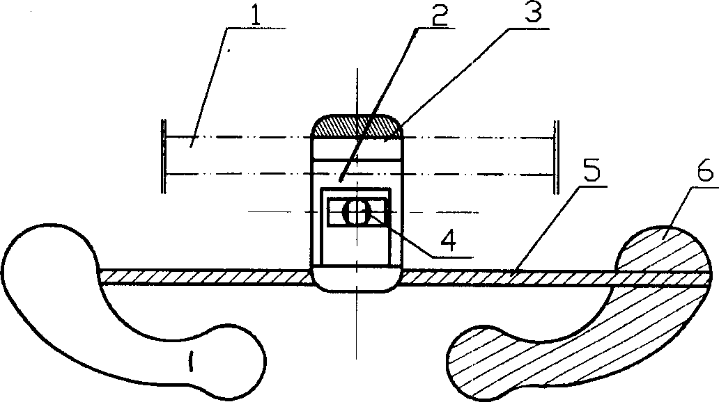
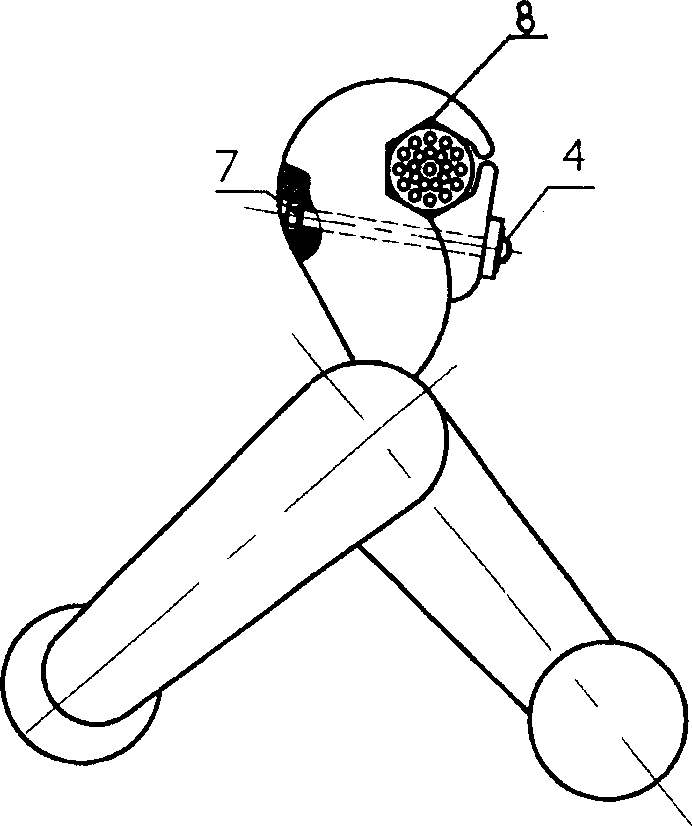
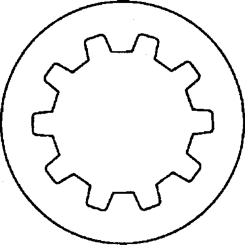
[0013] Embodiment: It is composed of wire clamp 2, steel strand 5, and hammer body 6. The wire clamp 2 adopts a two-half-circle Hafur structure, and the outer contour of the wire clamp 2 is smooth and excessive. The hexagonal hole 8 is provided with a left-handed anti-skid pattern 3, the lower end of the wire clamp 2 is die-cast in the middle of the steel strand 5, the hemispherical head bolt 4 passes through the wire clamp 2, and is fastened with a helical tooth-shaped anti-loosening anti-retraction ring 7 and a nut. The two ends of the steel strand 5 are die-casted together with the hammer body 6. The hammer body 6 is made of non-magnetic zinc alloy material and is in the shape of an elbow fist. The external contour of the hammer body 6 is smooth and excessive. The inner hole wall of the tooth-shaped anti-loosening and anti-retreating ring 8 is provided with helix angle anti-retraction teeth 9 corresponding to the hemispherical head bolt 4 thread pitches. Loosening and anti-...


PUM


Abstract

Disclosed is a vibration-proof hammer that comprises line clamp using two half circles structure; the outline of line clamp is circular and has hexagonal holes in which having left-handed anti-slip waves; lower end of the line clamp is die cast in the middle of steel strand and half sphere bolt goes through line clamp and get bound with spiral tooth anti-loose stop ring and nuts; the steel strand is die cast with the hammer body; when being elbow-fist type, the two hammer locate on 45-60 degree position. The invention has the advantages of low discharge from corona, low electromagnetic energy loss with the circular outline of the line clamp.

Description

technical field [0001] The invention relates to a metal fitting device for electric machinery protection, in particular to an anti-vibration hammer capable of alleviating wind vibration of an overhead transmission line. Background technique [0002] With the development of ultra-high voltage and large-capacity power transmission technology, the anti-vibration hammers currently used for electric machinery protection have poor anti-corona performance, large electromagnetic loss, unstable grip force, and are prone to displacement under the action of natural external forces, which seriously affects the use effect. Chinese patent 00255410.0 discloses a new type of combined anti-vibration hammer, which includes a wire clip, a steel strand, and a hammer head. The connecting end of the hammer head connected to the steel strand is provided with a connecting hole, and the steel strand is inserted into the connecting hole and fixed. , the other end of the ...

Claims


Application Information

Patent Timeline
IPC IPC(8): H02G7/14
Inventor 仝合泽
Owner 仝合泽
Why Eureka
Try Eureka