Roller for a fibre-processing machine

一种纤维处理、机械的技术,应用在罗拉领域,能够解决不适合圆筒端部和整个内部和毂部区域、难控制加载情况和操作条件等问题,达到宽工作宽度、改良减速值、高生产速度的效果

Inactive Publication Date: 2012-04-18
TRUTZSCHLER GMBH & CO KG
View PDF5 Cites 0 Cited by
  • Summary
  • Abstract
  • Description
  • Claims
  • Application Information

AI Technical Summary

Problems solved by technology

In addition, it is disadvantageous that in the case of high-speed rollers for fiber processing machines equipped with card clothing, it is difficult to control the loading situation and operating conditions (constant carding nip), so that the Rollers are not used for fiber handling machinery equipped with card clothing
Another disadvantage is that the fiber-reinforced plastic material is not suitable for the cylinder ends and the entire inner and hub area

Method used


Image

  • Roller for a fibre-processing machine
  • Roller for a fibre-processing machine
  • Roller for a fibre-processing machine

Examples


Embodiment Construction

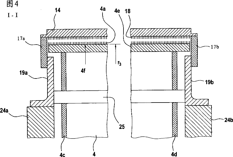
[0020] figure 1 Shows a flat card, for example a Trützschler TC 03 flat card, with feed roller 1, feed table 2, licker-in rollers 3a, 3b, 3c, cylinder 4, doffer 5, stripping roller 6, Rollers 7, 8, web guide elements 9, web funnel 10, draw-off rollers 11, 12, revolving card flats 13 with card flat deflection rollers 13a, 13b and card flat racks 14, cans 15 and rings Bar device 16. The curved arrows represent the direction of rotation of the rollers. Reference sign M represents the center (axis) of the cylinder 4 . Reference numeral 4a designates the card clothing and reference numeral 4b designates the direction of rotation of the cylinder 4 . Reference sign B represents the rotation direction of the rotary carding flat 13 in the combing position, and reference sign C represents the direction in which the carding flat rack 14 moves on the opposite side. Reference numerals 23', 23" designate fixed carding members, reference numeral 39 designates the hood below the cylinder...


PUM

PropertyMeasurementUnit
densityaaaaaaaaaa
diameteraaaaaaaaaa
coefficient of thermal expansionaaaaaaaaaa

Abstract

The present invention provides a roller for a fibre-processing machine, for example a spinning preparation machine such as a flat card, cleaner or the like, flock feeder, roller card, nonwoven-forming machine or the like, comprises a roller body. In order to make possible, by simple means, economical manufacture and adequate dimensional stability, for example a substantially constant carding nip,the roller body has at least one metal cylinder and at least one circular cylindrical sheath of fibre-reinforced plastics material surrounding the cylinder.

Description

technical field [0001] The present invention relates to a roller for fiber processing machines such as spinning preparation machines, loose fiber feeders, roller carding machines, nonwoven forming machines, etc., spinning preparation machines such as flat cards, cleaning machines etc., the rollers have walls of fibre-reinforced plastic material. Background technique [0002] The effective distance between the tip of the card clothing and the mechanical components arranged relative to the card clothing is called the carding nip. The mechanical component may also have a clothing, but instead it may be formed by a housing part with a guide surface. The carding nips are decisive for the carding quality. The size (width) of the carding nip is an essential mechanical parameter which influences the process (fiber handling) and the running characteristics of the machine. The carding nips are set as narrow as possible (it is measured in tens of millimeters) without creating the r...

Claims


Application Information

Patent Timeline
Patent Type & Authority Patents(China)
IPC IPC(8): D01G15/12D01G15/16
CPCF17C2209/2154D01G15/16D01G9/14D01G15/18D01G15/20
Inventor S·施利希特U·福尔拉特
Owner TRUTZSCHLER GMBH & CO KG
Why Eureka
Try Eureka