Fuel vapor vent valve float assembly and method of making same

A technology for exhaust valves and floats, which is applied to the direction of the float, lift valve, and valve device of the control valve, which can solve the problem of central part exposure

Inactive Publication Date: 2006-01-18
EATON INTELLIGENT POWER LTD
View PDF0 Cites 0 Cited by
  • Summary
  • Abstract
  • Description
  • Claims
  • Application Information

AI Technical Summary

Problems solved by technology

However, the mounting and retention of such a thin disc on the float, and the requirement to keep the central part of the disc exposed and resilient for closing the vent has been created during the mounting of the disc-shaped element on the float problem

Method used


Image

  • Fuel vapor vent valve float assembly and method of making same
  • Fuel vapor vent valve float assembly and method of making same
  • Fuel vapor vent valve float assembly and method of making same

Examples


Embodiment Construction

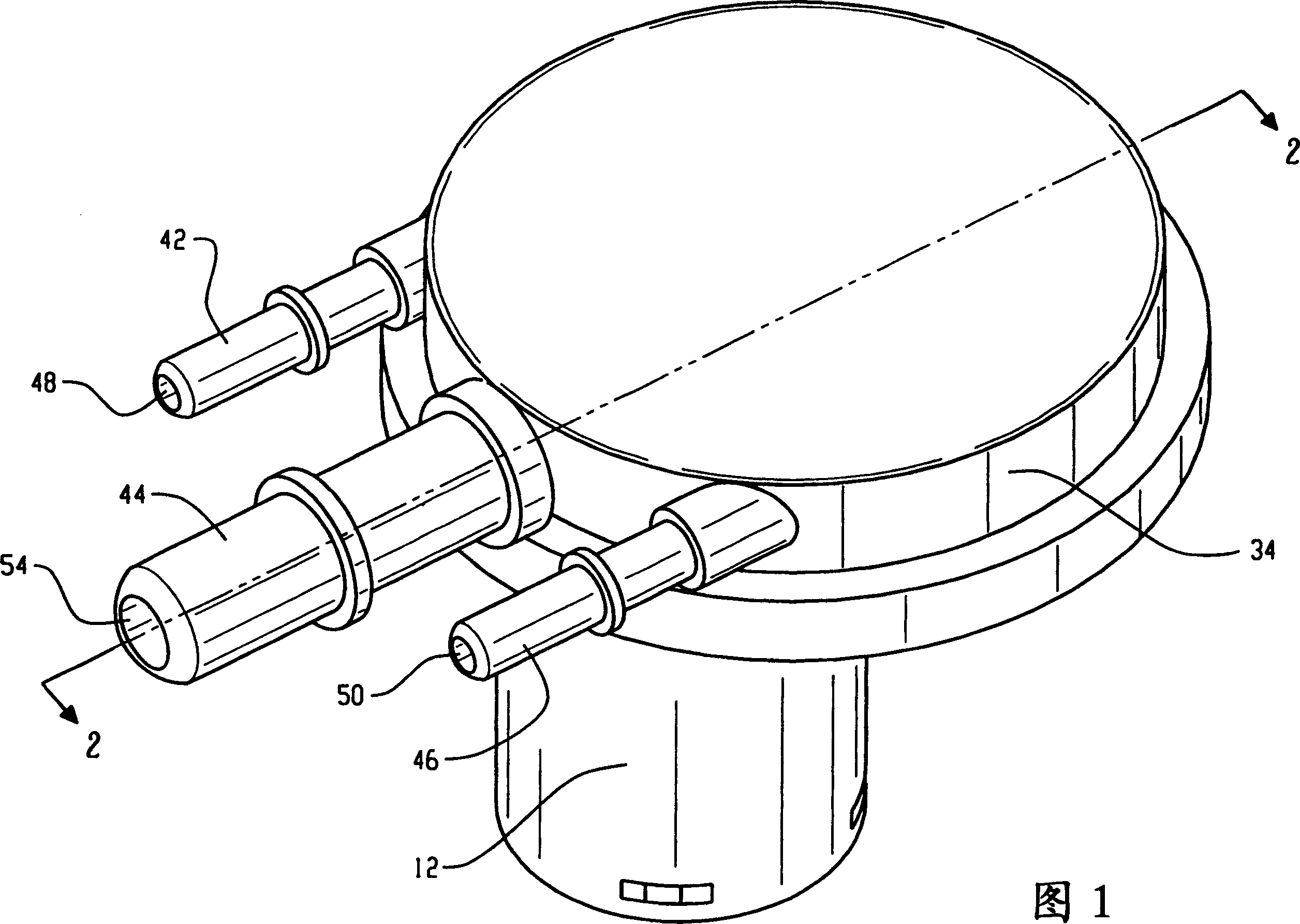
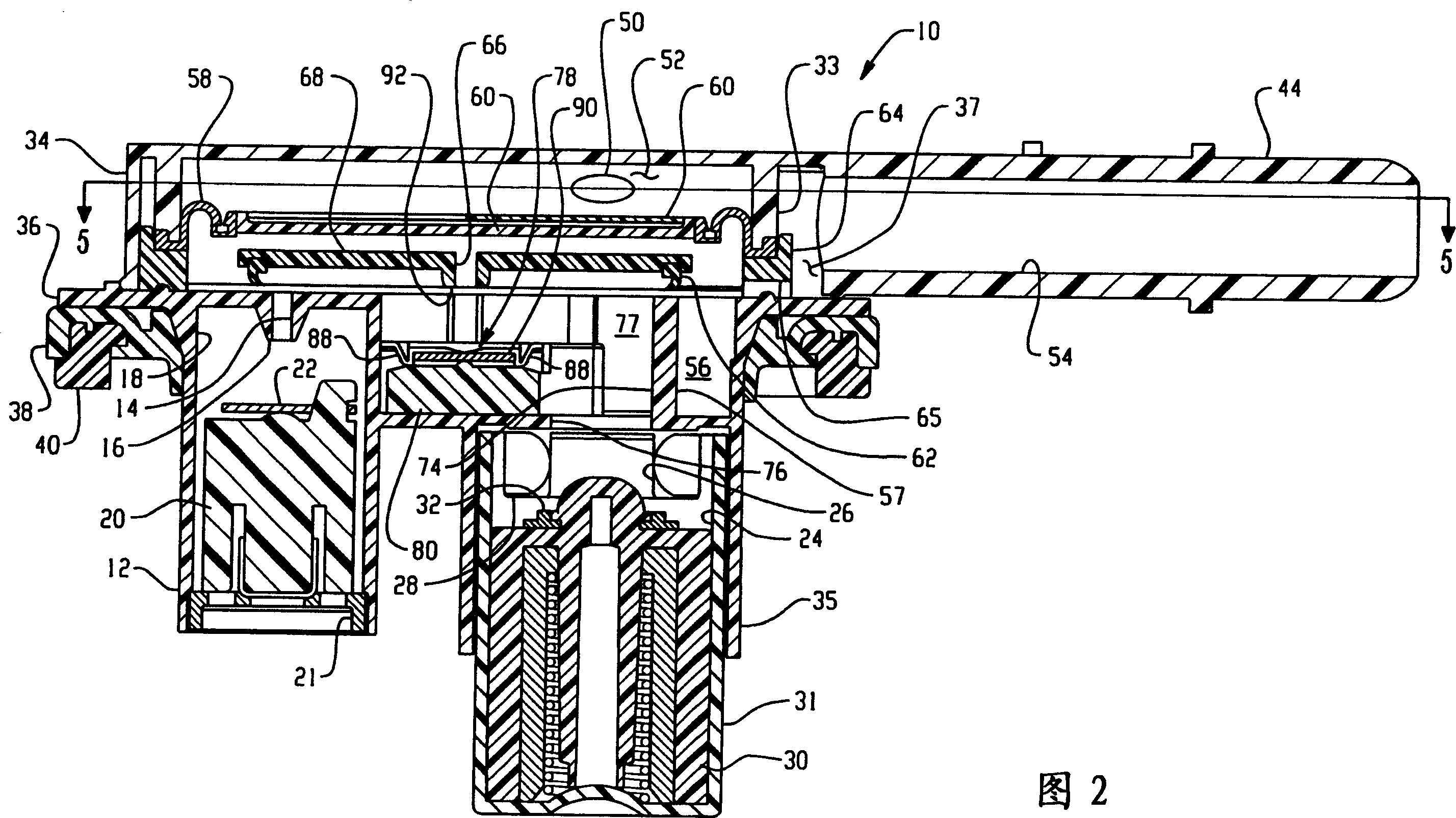
[0016] Referring to Figures 1 to 3, the multifunctional valve assembly, generally indicated at 10, includes a valve body 12 in which is formed a first vapor exhaust passage 14 with a valve seat 16 at the end of the passage 14. The valve seat 16 is arranged in a first position relative to the location of the valve via a mounting hole (not shown) through the wall of the fuel tank, not shown.

[0017] The valve body 12 defines a first float chamber 18 in which is provided a float 20 having a soft elastic valve element 22 arranged at the upper end of the float for raising the float of the valve and resting on the The passage 14 is closed when the valve seat 16 is on.

[0018] The valve body 12 also defines a second valve chamber 24 having a second exhaust passage 26 larger than the passage 14 , the lower end of which forms a valve seat 28 arranged at a lower position relative to the valve seat 16 . A floater assembly 30 is slidably disposed in the valve chamber 24; and, the float...


PUM


Abstract

A float assembly for a multifunction fuel vapor vent valve with a float having a recess formed in the upper surface of the float with a slot formed in the side of the float and communicating with the recess. A raised surface portion is formed in the bottom of the recess and downwardly extending projections are formed in the slot at the recess. A flexible wafer like valve disk is inserted in the slot and deformed or curled to pass under the projections and over the raised surface and into the recess. When fully received in the recess the disk returns to its flat configuration; and, the downward projections prevent removal without distortion. Radially inwardly projections about the recess retain the disk for limited lost motion in the direction of float movement.

Description

technical field [0001] The present invention relates to vapor vent valves (vent valves) for fuel tanks, in particular of the float-operated type for controlling the flow of fuel vapors from a fuel tank to a storage device, for example filled with granular carbonaceous matter canister. Background technique [0002] In providing such float-controlled vent valves for motor vehicle fuel tanks, it has been desired to provide a multi-function valve in a common assembly mounted to the fuel tank through a single mounting hole (access opening) so that the Vapor penetration is minimal at this connection. Such multi-function valves have included a variety of float control valves used to close different sized drain valves at different fuel levels in the fuel tank during refueling and in response to fuel sloshing in the fuel tank during vehicle operation. breath. [0003] Typically, such multifunction float control valves require a wide range of floats, sizes, movements and buoyancy t...

Claims


Application Information

Patent Timeline
Patent Type & Authority Applications(China)
IPC IPC(8): F16K31/22F16K33/00F16K1/00
CPCF16K24/044Y10T137/7426Y10T137/053Y10T137/3099Y10T137/6004B60K15/01
Inventor K·M·斯平克S·H·韦泽尔
Owner EATON INTELLIGENT POWER LTD
Why Eureka
Try Eureka