
Image display method and image display apparatus

一种图像显示、像场的技术,应用在图像通信、静态指示器、仪器等方向,能够解决图像质量变差等问题

Inactive Publication Date: 2006-01-04
PANASONIC CORP
View PDF1 Cites 1 Cited by
  • Summary
  • Abstract
  • Description
  • Claims
  • Application Information

AI Technical Summary

Problems solved by technology

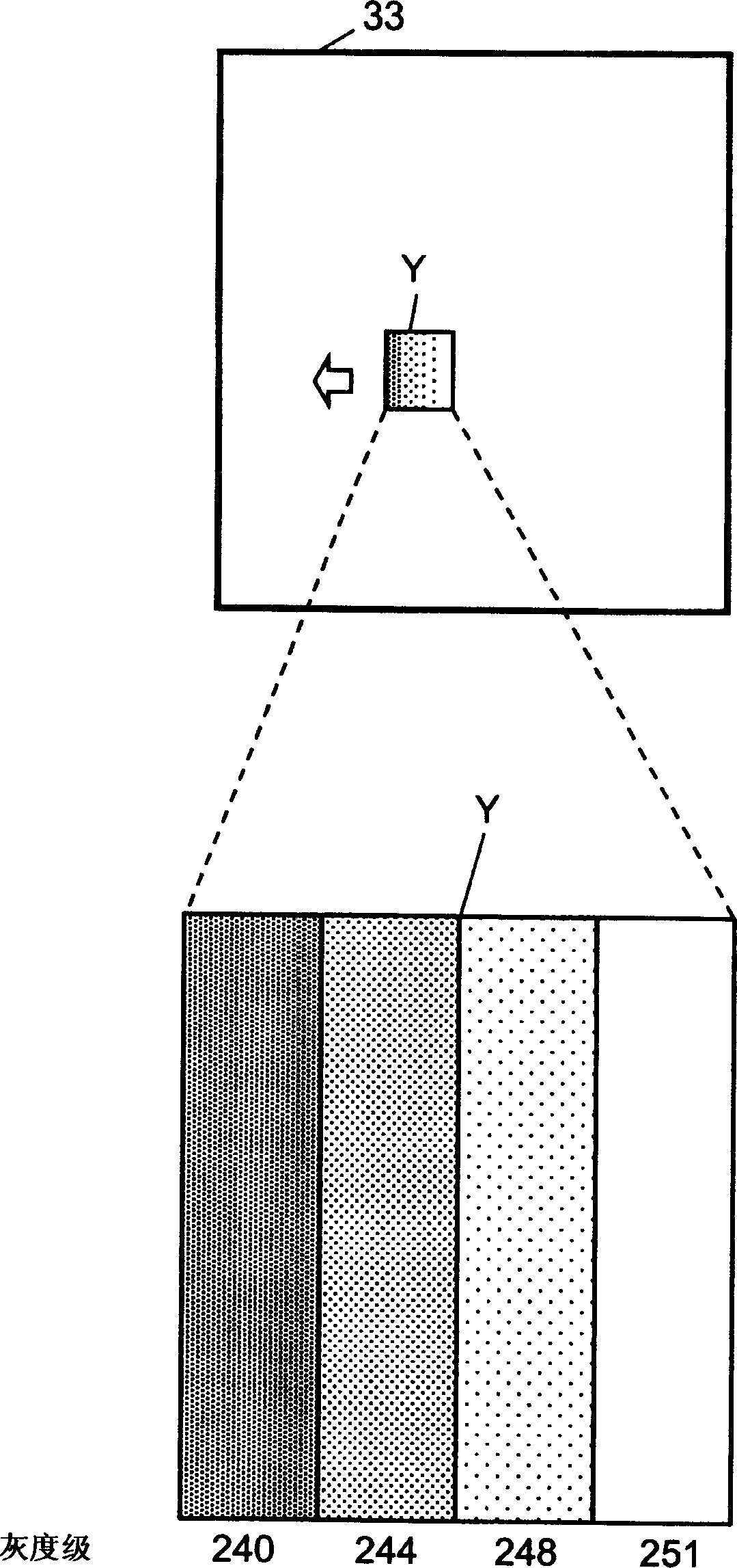
Conversely, if you want to suppress the pseudo-contour of a large moving image near the gray level where the pseudo-contour of the moving image occurs, the number of gray levels needs to be limited, and the number of gray levels that can be displayed decreases, resulting in a problem that the image quality deteriorates.

Method used


Image

  • Image display method and image display apparatus
  • Image display method and image display apparatus
  • Image display method and image display apparatus

Examples


Embodiment Construction

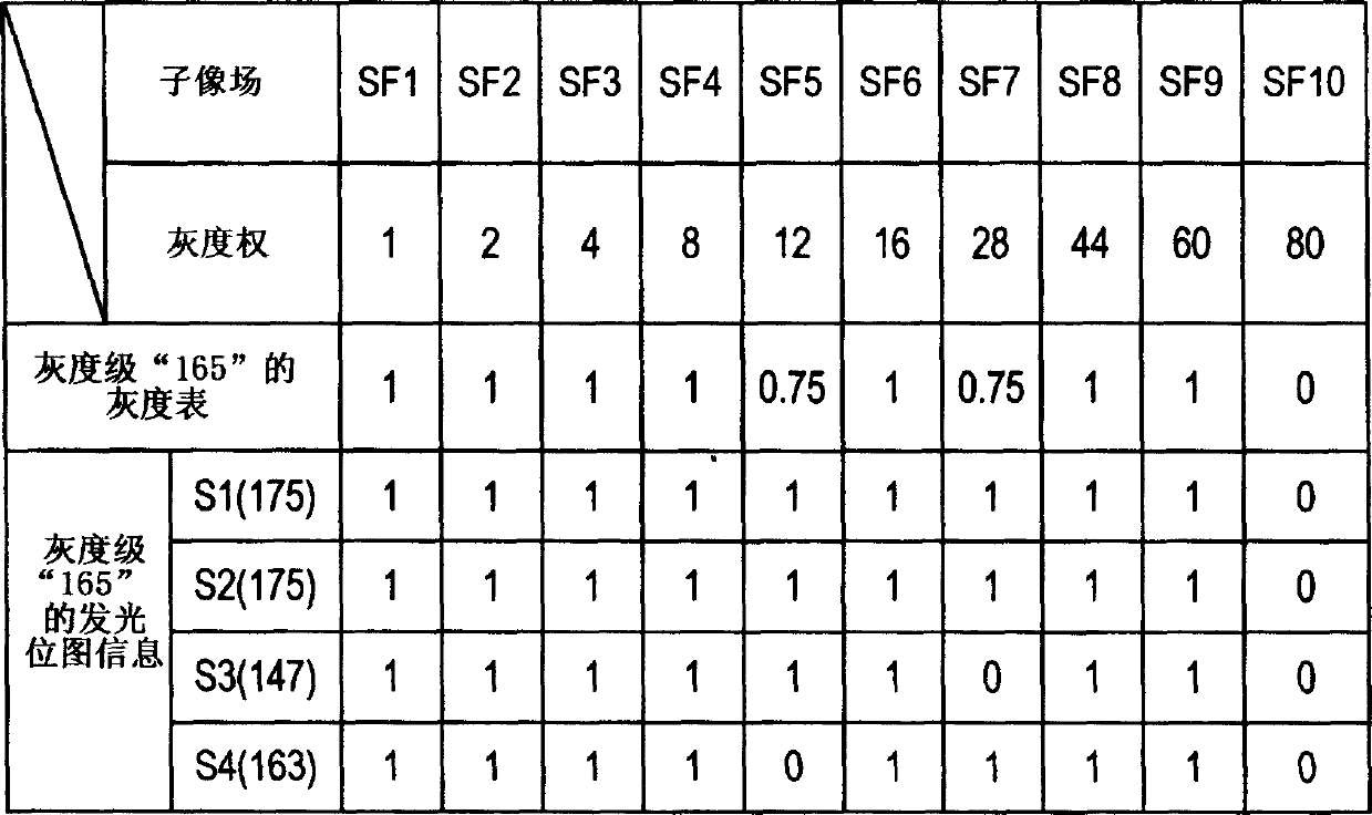
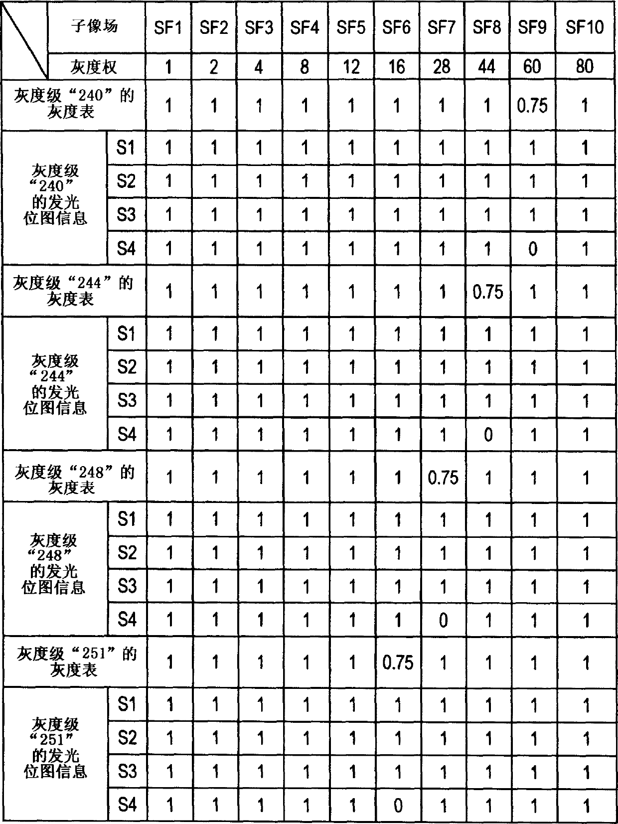
[0054]First, the idea of ​​the present invention to reduce the pseudo-contours of moving images will be described. Here, 1 image field is divided into 10 sub-image fields (SF1, SF2, ..., SF10), and the brightness weights of each sub-image field are 1, 2, 4, 8, 12, 16, 28, 44, 60, 80 case as an example.

[0055] As mentioned above, no matter how subtle the gray level changes, the pseudo-contour of the moving image always occurs in the part where the luminous bitmap information changes greatly. Therefore, if an image is displayed in a grayscale such that all the sub-image fields with a brightness weight smaller than the sub-image field to be emitted are uniformly illuminated, the change of the emission bitmap information becomes small, thereby suppressing pseudo-contours of moving images. happened.

[0056] The gradation levels satisfying this condition are specifically 11 kinds of gradation levels (0, 1, 3, 7, 15, 27, 43, 71, 115, 175, 255). For example, the gray level "27" ...


PUM


Abstract

An image display method wherein a lighting pattern information generator circuit (17) in an image display apparatus (1), which divides one field into a plurality of subfields and combines lightings or non-lightings of the subfields so as to display gradations, is used to generate a plurality of lighting pattern information in which the average lighting rate of all of subfields, which have smaller brightness weights than subfields having a average lighting rate that is not zero and having the maximum brightness weight, is greater than a predetermined value, and wherein a dither generator circuit (19) is used to subject the plurality of lighting pattern information to a time average processing and a spatial average processing to display all the gradations and reduce the moving-image pseudo-contours.

Description

technical field [0001] The invention relates to an image display method and an image display device for dividing an image of one image field into images of a plurality of sub-image fields for multi-level grayscale display. Background technique [0002] Plasma display screens (hereinafter referred to as "PDP"), digital mirror devices, and other image display devices that perform binary control of light emission or non-light emission, mostly use the sub-image field method for intermediate-level grayscale display. In the sub-field method, a plurality of sub-fields weighted by the number of times of light emission or the amount of light emission are used to time-divide one image field, and binary control is performed on each pixel for each sub-image field. That is, each sub-field has a predetermined brightness weight, and the method of displaying the gray scale is based on the sum of the brightness weights of the sub-fields that emit light. [0003]...

Claims


Application Information

Patent Timeline
Patent Type & Authority Applications(China)
IPC IPC(8): G09G3/20H04N5/66G09G3/28G09G3/291G09G3/296
CPCG09G2320/0266G09G3/2062G09G3/2029G09G3/28G09G3/2044G09G3/288G09G2320/0276G09G3/291G09G3/296
Inventor 山田和弘
Owner PANASONIC CORP
Learn More