Audio frequency magnetic conducted connection and connector thereof

An audio and magnetic permeation technology, which is applied in the field of audio magnetic permeation connection method and its device, can solve problems such as difficult management, high operating cost, and inability to guarantee, so as to achieve the disappearance of maintenance and operating costs, reduce equipment operating costs, and eliminate artificial damage effect

Inactive Publication Date: 2005-12-28
JIANGSU UNIV
View PDF0 Cites 2 Cited by
  • Summary
  • Abstract
  • Description
  • Claims
  • Application Information

AI Technical Summary

Problems solved by technology

[0002] The student earphone microphone used in the voice teaching equipment and the university computer room equipment is connected to the equipment by wired connection. The earphone microphone in the student unit is hung on the seat, and the students in the school share the earphone microphone in the classroom. The curiosity of the engineering students is strong. The earphone microphone is used as the object of fiddling in class, resulting in a high rate of damage to the earphone microphone of students. In addition, it is difficult to manage, and the loss phenomenon is serious, which directly affects the safe operation of the voice teaching equipment, and thus affects the normal teaching order. Increased the management difficulties of large-scale use of language labs, high operating costs, resulting in many colleges and universities teaching foreign language listening courses can not be guaranteed in the language room
[0003] In addition, the earphone microphones in computer rooms in universities have the same problem, and the phenomenon of damage and loss is serious, so that many computer rooms dare not install earphone microphones, or use the method of students to bring their own earphone microphones for independent learning, etc.
When students bring their own earphones and microphones, the socket on the PC is seriously damaged due to frequent plugging and pulling out of the plug.

Method used


Image

  • Audio frequency magnetic conducted connection and connector thereof
  • Audio frequency magnetic conducted connection and connector thereof
  • Audio frequency magnetic conducted connection and connector thereof

Examples


Embodiment Construction

[0016] The following examples will further illustrate the present invention, but do not limit the present invention thereby.

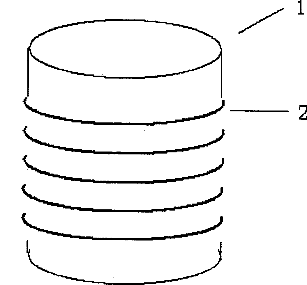
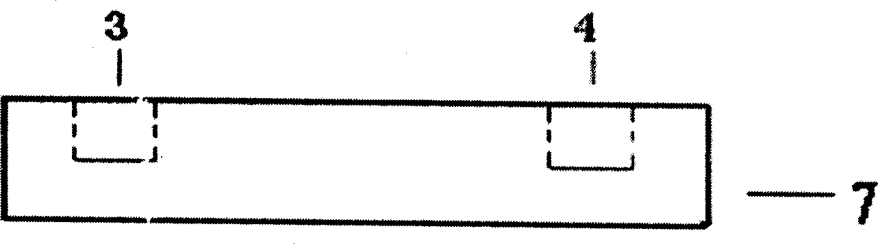
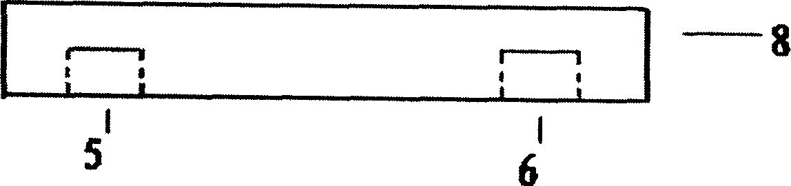
[0017] Install an audio magnetic guide (7) additionally on each student's desk or computer room table in the language room, set a microphone signal receiving coil (3) and an earphone signal transmitting coil (4) in the audio magnetic guide (7) ), the two coils have the same structure, and the enameled wire (2) with a DC resistance of 12Ω is respectively wound on the low-frequency magnetic core (1) to form a coil, such as figure 1 As shown, place the two coils on the top of the audio magnetic guide (7), and make the distance between the two coils 30mm, such as figure 2 As shown, the microphone signal receiving coil (3) is connected to the microphone input interface on the speech lab desk or the computer room desk through lead wires, and the earphone signal transmitting coil (4) is connected to the earphone output port on the speech lab desk or computer...


PUM


Abstract

The earphone signal is loaded into the earphone signal emission coil to generate audio magnetic field, which is received by earphone signal receiving coil in earphone signal amplifying circuit and is transformed into audio voltage signal. Then the signal is loaded into amplifying circuit to drive earphone. Meanwhile the mic in the mic-earphone amplifying circuit picks up the speech of student and sends it into amplifier of mic. After amplifying, it drives mic signal emission coil to generate audio magnetic field. The mic signal is received by mic signal reception coil and is transformed into audio signal of mic that is loaded into the mic plug in socket.

Description

technical field [0001] The invention relates to phonetic teaching equipment and university computer room equipment, in particular to an audio magnetic conduction connection method and device between earphone microphones, voice teaching equipment and university computer room equipment. Background technique [0002] The student earphone microphone used in the voice teaching equipment and the university computer room equipment is connected to the equipment by wired connection. The earphone microphone in the student unit is hung on the seat, and the students in the school share the earphone microphone in the classroom. The curiosity of the engineering students is strong. The earphone microphone is used as the object of fiddling in class, resulting in a high rate of damage to the earphone microphone of students. In addition, it is difficult to manage, and the loss phenomenon is serious, which directly affects the safe operation of the voice teaching equipment, and thus affects the...

Claims


Application Information

Patent Timeline
Patent Type & Authority Applications(China)
IPC IPC(8): H04R3/00
Inventor 胡斌李凤华李正明
Owner JIANGSU UNIV
Why Eureka
Try Eureka