Ultraviolet radiant sensor system with sterilizer

A technology for sterilization and disinfection devices and sensing systems, which is applied in the field of optical sensing systems, can solve the problems of reduced sensor sensitivity, accumulated dirt, and decreased ability of sensors to detect ultraviolet radiation, so as to reduce the loss of water pressure head and promote maintenance. Effect

Inactive Publication Date: 2005-12-28
SHENZHEN OCEAN POWER INDUSTRIAL CO LTD
View PDF0 Cites 3 Cited by
  • Summary
  • Abstract
  • Description
  • Claims
  • Application Information

AI Technical Summary

Problems solved by technology

[0008] Second, when it is urgent to use ultraviolet disinfection systems to treat relatively low water quality (such as low-quality sewage from urban sewage treatment plants), a problem arises: many parts of the disinfection system that have been in close contact with sewage will accumulate dirt
[0009] In detail, when the sensor accumulates dirt, the ability of the sensor to detect UV radiation is reduced, the sensitivity of the sensor is reduced, and the operator may miss the signal of a reading (that is, what appears to be a small change in the reading is actually a large change), and in fact one or more radiation sources are no longer functioning
It is therefore questionable to have a cleaning device at the sensor window in the sewage flow, as it would impede the flow of the sewage and become an attachment point for dirt and clogging

Method used


Image

  • Ultraviolet radiant sensor system with sterilizer
  • Ultraviolet radiant sensor system with sterilizer
  • Ultraviolet radiant sensor system with sterilizer

Examples


Embodiment 1

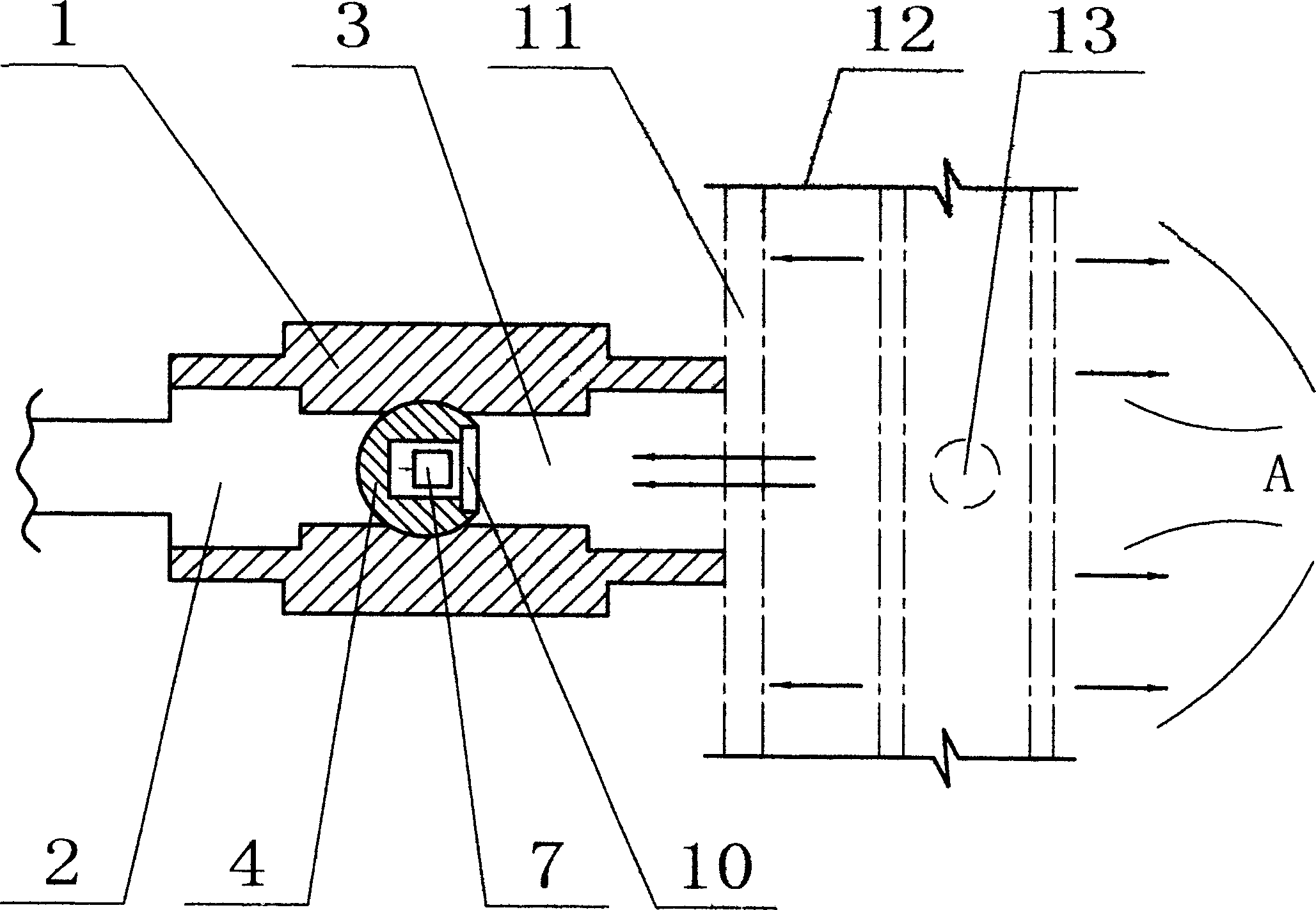
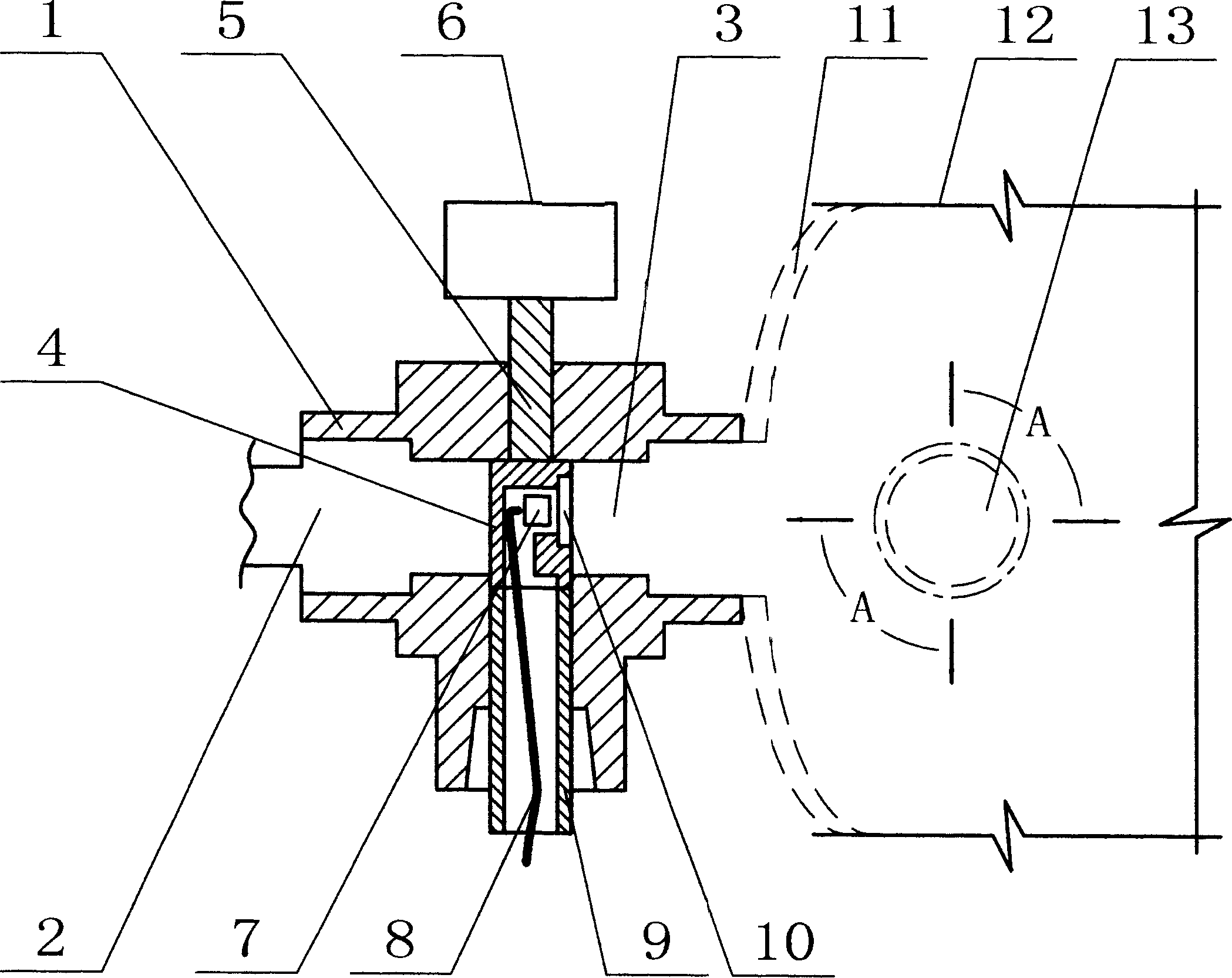
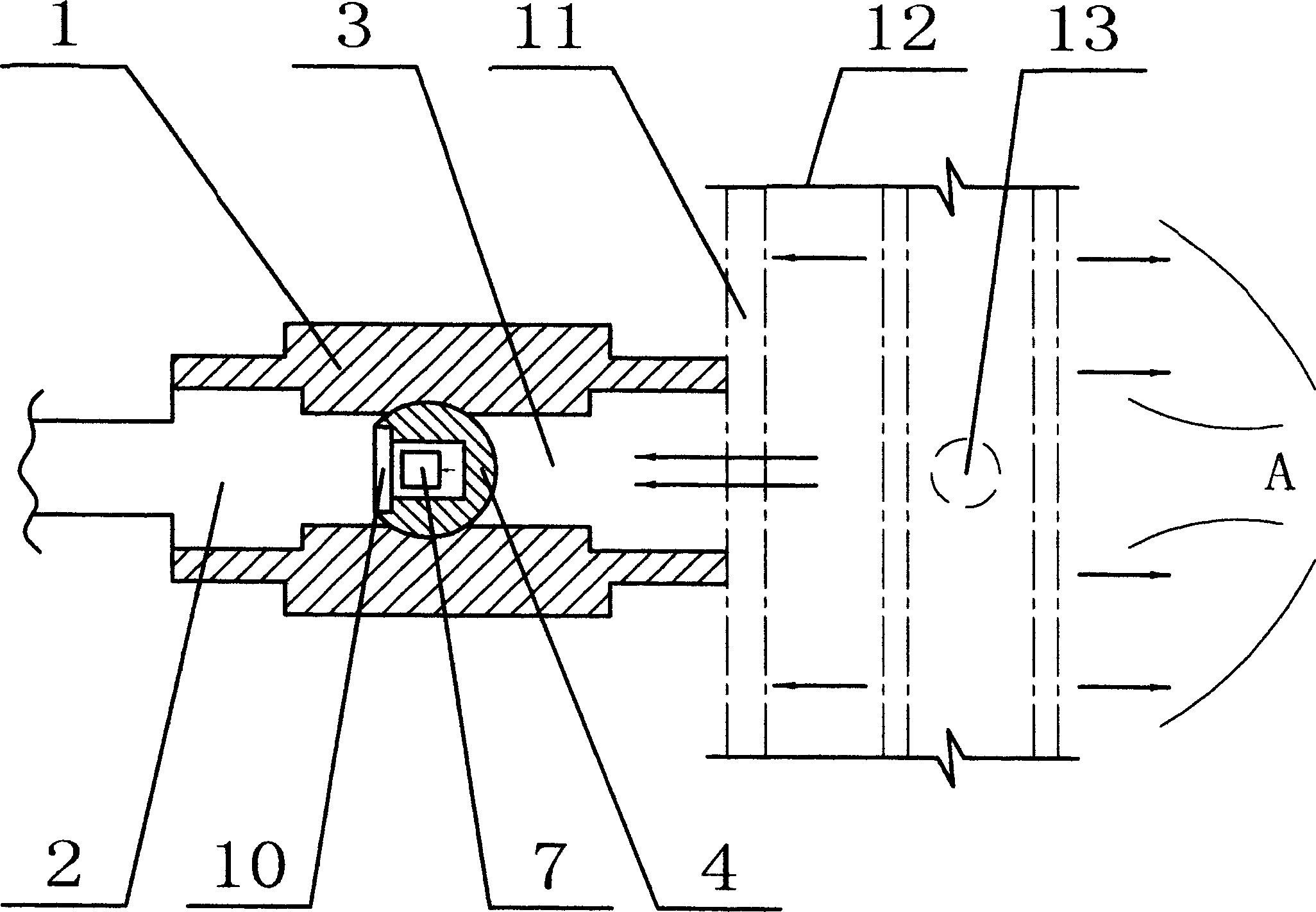
[0035] Figure 1~4 A first embodiment of an ultraviolet radiation sensing system is described. figure 1 and figure 2 illustrates the first embodiment of the sensing system in the first or detection position, while image 3 and Figure 4 The first embodiment of the sensing system in the second or cleaning position is illustrated.

[0036] Such as Figure 1~4 As shown, the ultraviolet radiation sensing system mainly includes a casing (1), and a first cavity (2) and a second cavity (3) are arranged in the casing (1), and the first cavity (2) and the second cavity A sensing device casing (4) is inserted between the two cavities (3). The sensing device housing (4) is connected to the motor (6) through a shaft (5).

[0037] A sensing photosensitive diode (7) is arranged in the sensing device casing (4), and the sensing photosensitive diode (7) is connected on the cable (8). The sensing photodiode can detect and respond to ultraviolet radiation with a wavelength in the range ...

Embodiment 2

[0045] Figure 5-8 A second embodiment of an ultraviolet radiation sensing system is illustrated, Figure 5 and Figure 6 illustrates the second embodiment of the sensing system in the first or detection position, while Figure 7 and Figure 8 A second embodiment of the sensing system in the second or cleaning position is illustrated.

[0046] Such as Figure 5-8 As shown, the ultraviolet radiation sensing system mainly includes a casing (14), and a first cavity (15) and a second cavity (16) are arranged in the casing (14), and the first cavity (15) and the second cavity A spherical casing (17) is inserted between the two chambers (16), and the spherical casing (17) is connected on the motor (19) by a shaft (18).

[0047] A sensing photodiode (20) is arranged in the spherical casing (17), and the sensing photodiode (20) is connected on the cable (21). The cable (21) is drawn out from the conduit (22) connected on the casing (14). The spherical casing (17) is also provid...


PUM


Abstract

A ultraviolet radiation sensor system with sterilizer consists of sensor and sterilizer. Sensor is used to test radiation degree of radiation field and response to radiation, the device consists of a window to radiation field, which moves from internal radiation field to external radiation field, when window moves to external radiation field and is connected to sterilizer, and sterilizer starts and removes scale from window. It can be a chemical sterilizer, a mechanical sterilizer or mixed sterilizer.

Description

technical field [0001] The invention relates to a light sensing system, in particular to an ultraviolet radiation sensing system with a sterilizing device. Background technique [0002] Optical radiation sensing devices have been widely used, mainly in ultraviolet radiation sewage disinfection systems. [0003] If the product of a given radiation intensity and the exposure time at this intensity is greater than the minimum dose (expressed in milliwatts per square centimeter), ultraviolet rays can sterilize water by irradiating it and killing microorganisms in the water. According to this principle, the ultraviolet disinfection system disinfects water to meet people's various needs for water. [0004] Typically sewage is passed through a pressurized stainless steel chamber filled with UV radiation for disinfection. The treatment modules in a UV disinfection system are submerged in an open channel in which wastewater is exposed to radiation while pass...

Claims


Application Information

Patent Timeline
IPC IPC(8): C02F1/32
Inventor 张坤赵欣平何唯平
Owner SHENZHEN OCEAN POWER INDUSTRIAL CO LTD
Why Eureka
Try Eureka