Optical film and polarizing film using the same, and method for improving view angle of the polarizing film
A technology of optical film and polarizing element, which is applied in the direction of optics, polarizing element, nonlinear optics, etc., and can solve problems such as light leakage, absorption of polarizing film on the outgoing side, viewing angle dependence of polarizing element or polarizing film, etc.
- Summary
- Abstract
- Description
- Claims
- Application Information
AI Technical Summary
Problems solved by technology
Method used
Image
Examples
example 1
[0092] The solution that the solid fraction concentration is 20% is by in the mixed solvent of the toluene of 300 parts by weight and the cyclohexanone of 100 parts by weight, dissolves 23.5 parts by weight and 70.5 parts by weight respectively shown in chemical formula (1) and (2) The UV-curable liquid crystal compound described in WO97 / 44703, and a mixture of 6 parts by weight of photopolymerization initiator Irga-cure 907 (Ciba Specialty Chemicals Company) were prepared.
[0093] (chemical formula 1)
[0094]
[0095] (chemical formula 2)
[0096]
[0097]The solution was applied on the polarizing element side of an iodide-based polarizing film manufactured by Polatechno Corporation (15% borate content in polyvinyl alcohol having a degree of polymerization of 1700 and a thickness of about 20 μm after stretching; A polyvinyl alcohol film was bonded to one side of a cellulose triacetate film treated with an alkali as a surface layer of a protective film by using a poly...
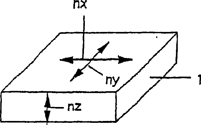
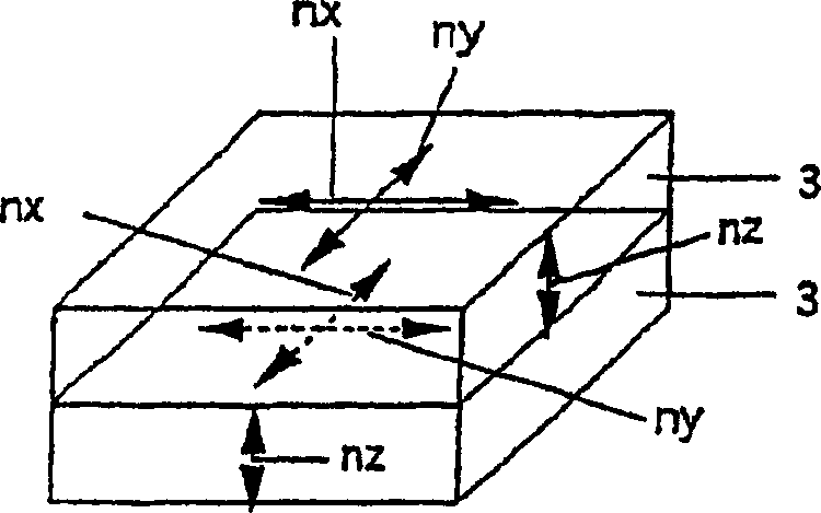
example 2
[0099] Polarizing film of the present invention obtains with the same method as example 1, except a piece of polarizing film, or polycarbonate film, uses PSA to be used in the polarizing film of example 1 (Δn p d p =39nm) of the first retardation film surface is laminated so that n x The direction is aligned with the direction of the absorption optical axis of the polarizing element. The refractive index n of the second retardation film in the direction showing the maximum in-plane refractive index x is 1.5864, the refractive index n in the direction perpendicular to the direction just mentioned y is 1.5844, the refractive index n in the thickness direction z is 1.5841, the thickness d is 70μm, and at 550nm (n x -n y )·d is 140nm. This polarizing film was bonded to the iodide-based polarizing film (manufactured by Polatechno Corporation) used in Example 1 with PSA so that the absorption optical axes of the polarizing elements were perpendicular to each other. The polari...
example 3
[0101] The first retardation film (Δn) prepared by the same procedure as in Example 1 p d p = 65 nm) was bonded to the third retardation film, or a cellulose triacetate film having an adhesive film layer on one side and the surface layer was treated with alkali, and the first retardation film was peeled off from the polarizing element. The refractive index n of the cellulose triacetate film in the direction showing the maximum in-plane refractive index x is 1.49522, the refractive index n in the direction perpendicular to the direction just mentioned y is 1.49517, the refractive index n in the thickness direction z (n e ) is 1.49461, thickness d n 80μm, average in-plane refractive index n 0 is 1.49520, in relation n e -n 0 =Δn n Down, |Δn n dn n | is 49nm. Then, the second retardation film, or used in Example 1 at 550nm (n x -n y ) A polycarbonate film whose d is 140 nm is laminated with PSA on the first retardation film side of the laminated structure of the peel...
PUM
| Property | Measurement | Unit |
|---|---|---|
| Thickness | aaaaa | aaaaa |
| Thickness | aaaaa | aaaaa |
| Thickness | aaaaa | aaaaa |
Abstract
Description
Claims
Application Information
 - R&D
- Intellectual Property
- Life Sciences
- Materials
- Tech Scout
- Unparalleled Data Quality
- Higher Quality Content
- 60% Fewer Hallucinations
Browse by: Latest US Patents, China's latest patents, Technical Efficacy Thesaurus, Application Domain, Technology Topic, Popular Technical Reports.
© 2025 PatSnap. All rights reserved.Legal|Privacy policy|Modern Slavery Act Transparency Statement|Sitemap|About US| Contact US: help@patsnap.com


