Leading edge feeder

A front edge, resting technology, applied in the directions of transportation and packaging, object separation, pile separation, etc., can solve the problems of complex, expensive, and complex guiding structure beams, and achieve the effect of precise and simple processing positions.

Active Publication Date: 2005-11-09
MABEG SYST GMBH
View PDF1 Cites 3 Cited by
  • Summary
  • Abstract
  • Description
  • Claims
  • Application Information

AI Technical Summary

Problems solved by technology

The device is complex because the delivery stroke of the stroke-drawing nozzle has to be provided with a very long guide structure and the linear motor has to be correspondingly bulky
A further disadvantage is that the coil elements are guided inside the beam and that the guide structure and the beam are correspondingly complex and expensive due to the accommodating of the magnets.
[0005] In addition, this device is only suitable for a device that extracts a sheet-like stream at the rear edge when separating the sheets or for extracting individual sheets when extracting the sheets from the leading edge.

Method used


Image

  • Leading edge feeder
  • Leading edge feeder
  • Leading edge feeder

Examples


Embodiment Construction

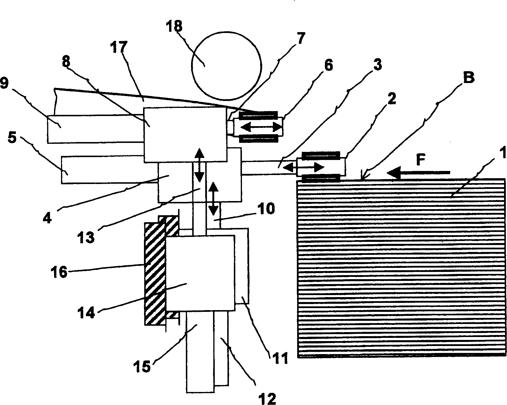
[0018] figure 1 A sheet separating device in the form of a front edge separating device is shown. This front edge separating device is arranged corresponding to the front edge of a stack 1 in the transport direction F of the sheets B to be separated into individual sheets. The separated sheets B are transported in a transport direction F to a machine for processing the sheets B, not shown here. For this purpose, the sheet B is usually conveyed via a transport table 17, for example a suction belt table. In order to reliably transfer the sheet B from the front edge separating device to the transport table 17, a so-called timing roller 18 can be provided here. By means of the beat rollers 18, the conveyed individual sheets are fixed on the transport table 17 in the beat of the arrival of the sheets for further transport.

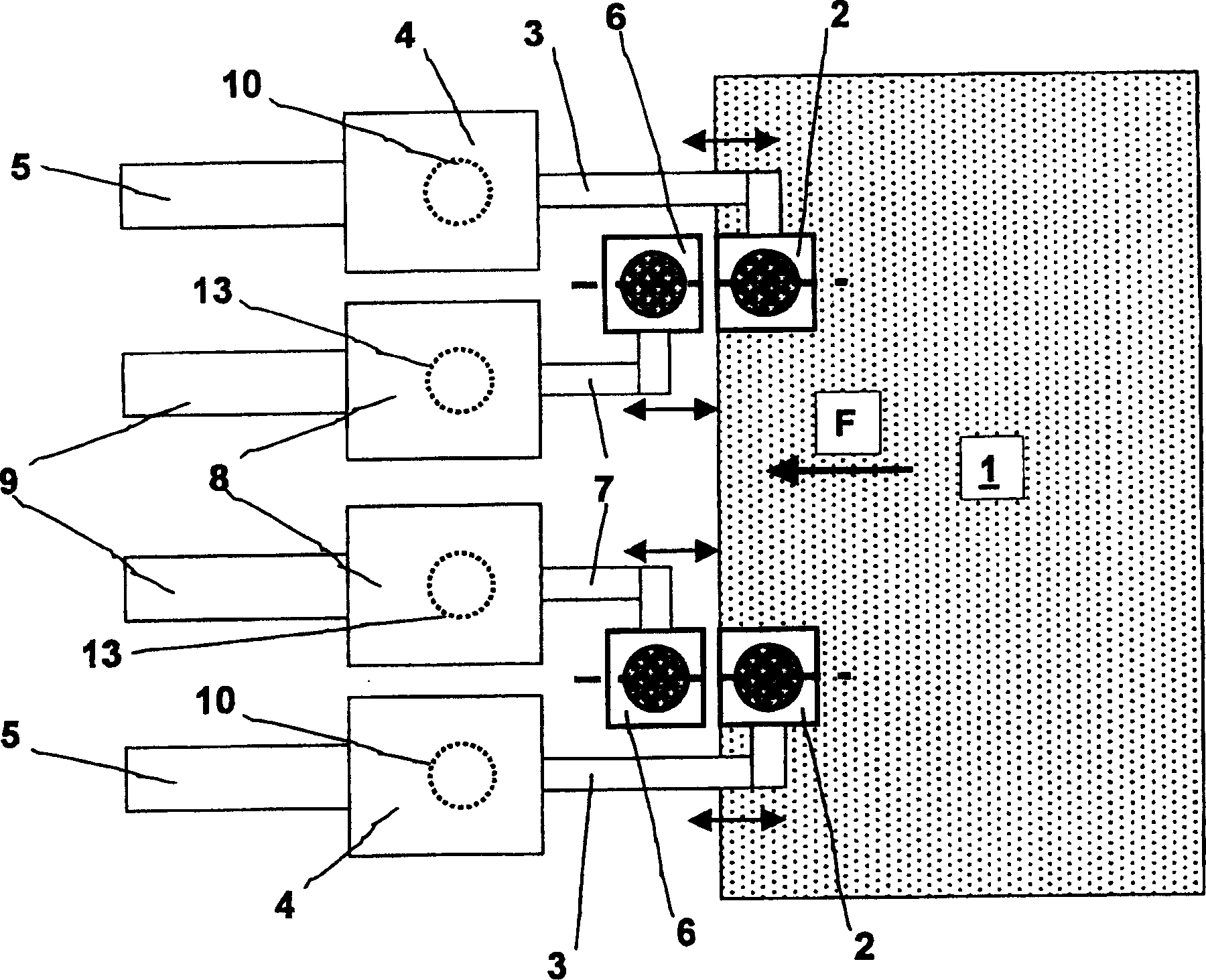
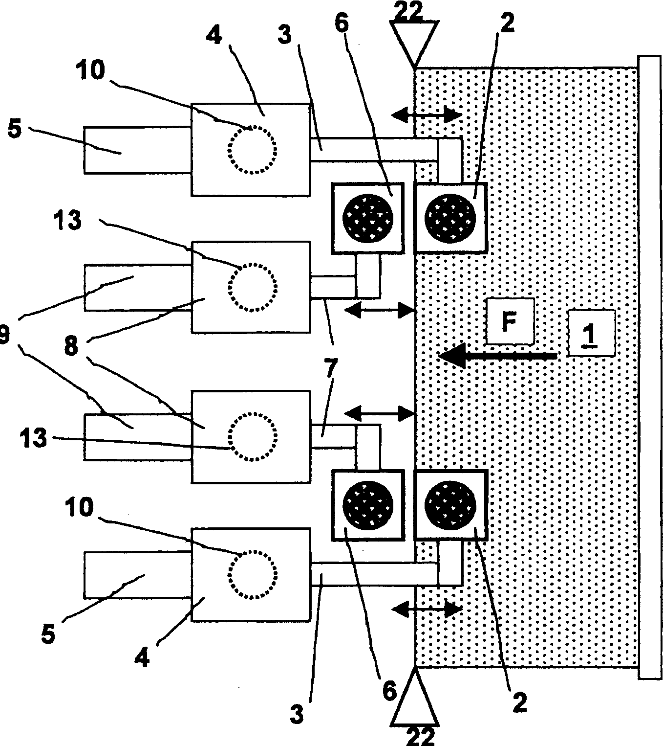
[0019] The front edge separating device of the present invention is provided with a plurality of suction nozzle driving devices. On the paper stack 1 , a f...


PUM


Abstract

A sheet feed device according to the present invention applied to a sheet processing machine is to extract paper sheets from a stack based on the principle of front edge separation. In order to improve the controllability for sheet separation of an extracting device at the stack 1 and transportation of the sheets, drive devices are provided separately for dual suction devices 2 and 6 led mutually about the mating parties in the sheet cycles. Therefore, the dual suction devices 2 and 6 are equipped with linear motors 12 and 15 to make lifting and linear motors 5 and 9 for the transporting movement. By this profitable method, the moving cycles can be established independently for the respective dual suction devices 2 and 6.

Description

technical field [0001] The invention relates to a device according to the preamble of claim 1 and a method according to the preamble of claim 7 . Background technique [0002] In DE-PS 842 349 a device for forming a continuously flowing sheet track from laminar echelons of sheets is known. The device shows a sheet separating device above the front end of a stack from which the sheets are to be separated into individual sheets and fed to a machine for processing the sheets. For this purpose the device has two pairs of so-called double suction nozzles (pairs of suction nozzles). Each double suction nozzle has a respective suction cup on its lower side and on its upper side. The double suction nozzles are connected in pairs on the lever drive, that is, each pair of suction nozzles can not only be installed on the upper surface in the area of ​​the front edge of the stack but also can remove a sucked sheet from the paper. Lifted on the upper side of the stack. In addition, w...

Claims


Application Information

Patent Timeline
Patent Type & Authority Applications(China)
IPC IPC(8): B65H3/08
CPCB65H3/0833B65H3/0883
Inventor R·布舒尔特R·多恩巴赫J·蒂策
Owner MABEG SYST GMBH
Why Eureka
Try Eureka