Digital single-lens reflex camera

A digital camera and single-reflection technology, applied to cameras, camera bodies, static cameras, etc., can solve problems such as inconstant settings

Inactive Publication Date: 2005-11-02
OLYMPUS CORP
View PDF2 Cites 7 Cited by
  • Summary
  • Abstract
  • Description
  • Claims
  • Application Information

AI Technical Summary

Problems solved by technology

Therefore, there is a problem that the prescribed time (ie, waiting time) from after the shutter release operation is performed to before the exposure is performed cannot be constantly set.

Method used


Image

  • Digital single-lens reflex camera
  • Digital single-lens reflex camera
  • Digital single-lens reflex camera

Examples


Embodiment Construction

[0033] Hereinafter, the present invention will be described based on illustrated embodiments.

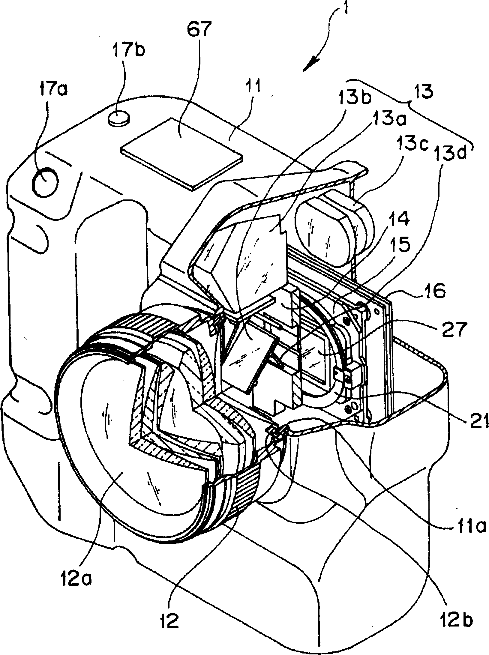
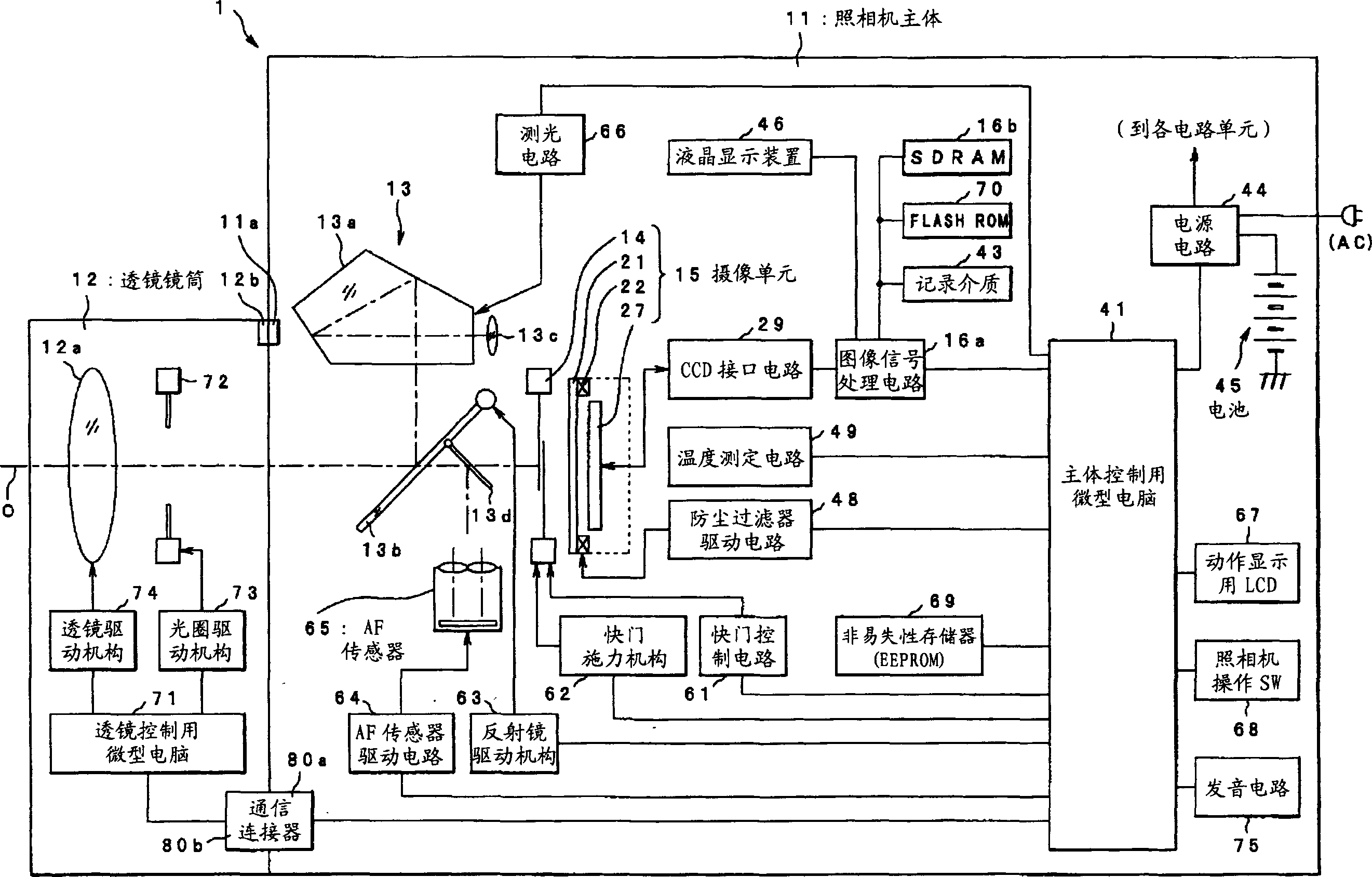
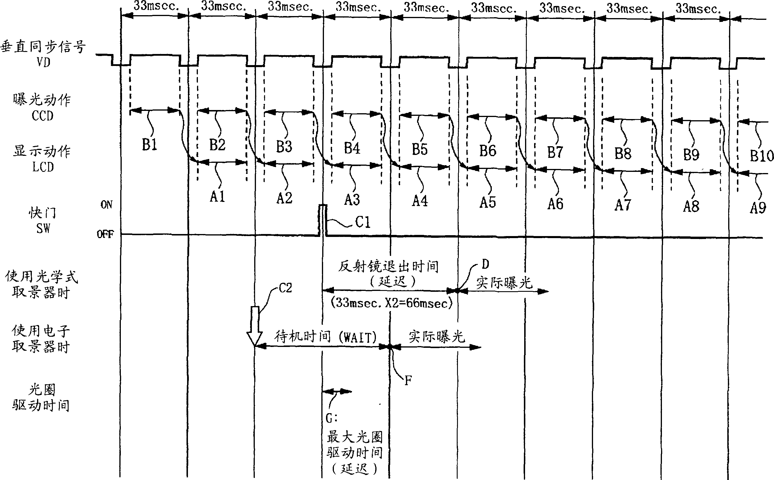
[0034] figure 1 and figure 2 It is a schematic configuration diagram of a single-reflection digital camera according to an embodiment of the present invention. in, figure 1 It is a perspective view schematically showing the internal structure of the single-reflection digital camera of this embodiment with a part cut away. figure 2 is outlined figure 1 A structural block diagram of the main circuit structure of a single-reflection digital camera. image 3 This is a timing chart for explaining the operation when the liquid crystal display device is used as an electronic finder in the camera of this embodiment. Figure 4 It is a flowchart of the processing procedure when setting the maximum aperture driving time in this embodiment.

[0035] A single-reflection digital camera (hereinafter simply referred to as a camera) 1 of this embodiment is composed of a camera body 11 and a ...


PUM


Abstract

A digital single-lens reflex camera comprises: an optical viewfinder; a retractable movable mirror for guiding subject images to the optical viewfinder; an image display device, serving as an electronic viewfinder, for displaying a subject image captured by an image-capturing device with the movable mirror retracted from the optical path; and a control device for starting image data acquisition with the image-capturing device after elapsing of a predetermined time, taking into consideration the amount of time necessary for the movable mirror to be retracted from the optical path and maximum diaphragm driving time of a diaphragm driving unit, following the user making a releasing operation while displaying a moving image on the image display device. This realizes a digital single-lens reflex camera which allows settings wherein the shutter release time lag is constantly the same, regardless of whether the optical viewfinder or the electronic viewfinder is used.

Description

technical field [0001] The present invention relates to a single reflex digital camera, and more particularly to a single reflex digital camera having an electronic viewfinder for displaying moving images based on image data continuously output from an imaging element using a display device. Background technique [0002] At present, a still image photographing device (hereinafter referred to as a digital camera) has practicality and is widely popularized. This photographing device is constituted in such a way that a light beam from an object to be photographed (hereinafter referred to as an object light beam) is incident on a camera composed of a plurality of lenses. In the imaging optical system composed of groups, the formed subject image is imaged at a predetermined position (for example, the light-receiving surface of an imaging element such as a charge-coupled device (CCD, Charge Coupled Device)), thereby obtaining a desired subject image, And record it in a prescribed ...

Claims


Application Information

Patent Timeline
IPC IPC(8): G03B19/12G03B9/02G03B17/00H04N5/225H04N5/232H04N101/00
CPCG03B19/12H04N5/2254H04N5/232H04N23/55H04N23/63
Inventor 小杉山嗣基
Owner OLYMPUS CORP
Why Eureka
Try Eureka