
Cooling cycle apparatus and method of controlling linear expansion valve of the same

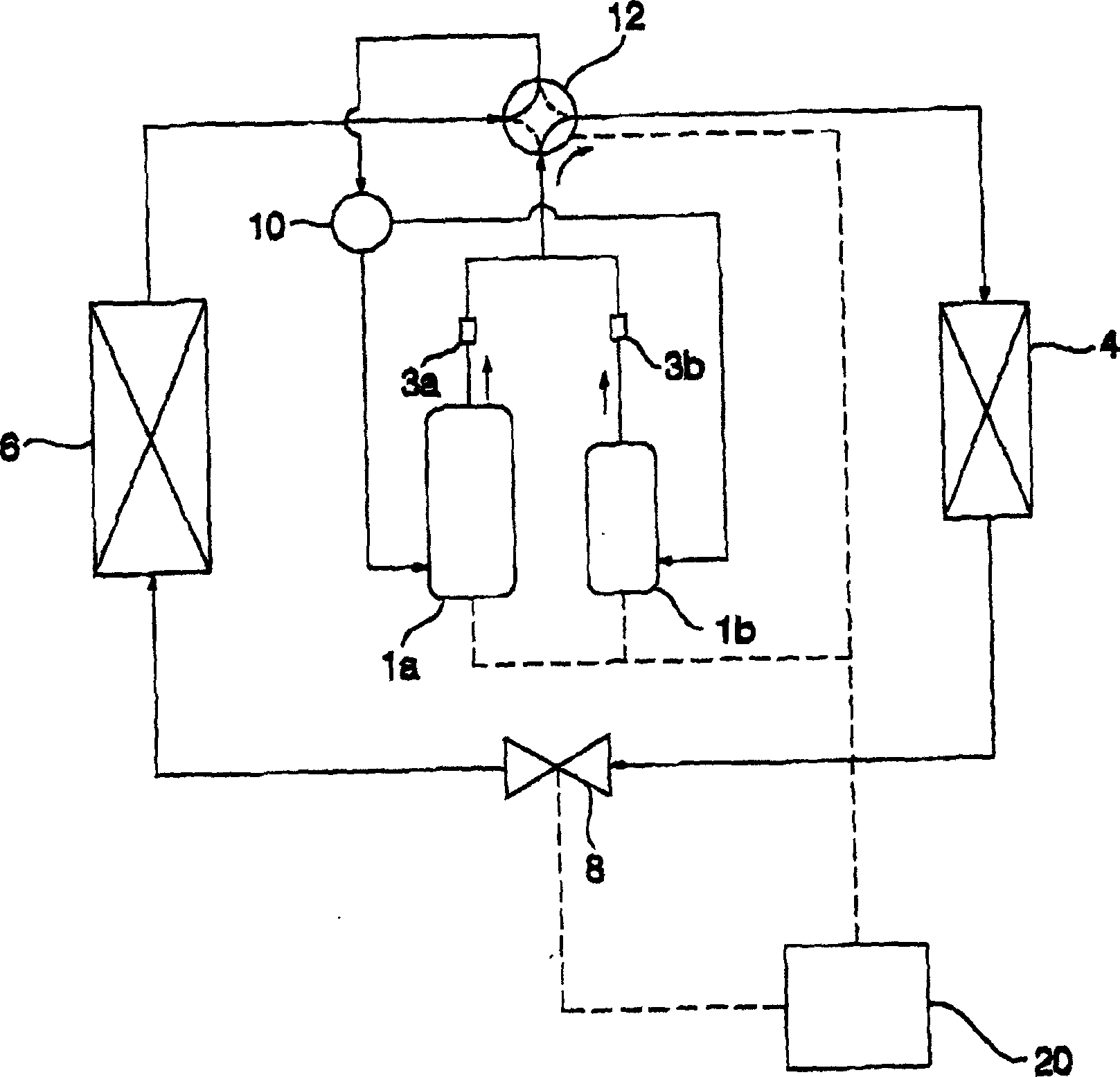
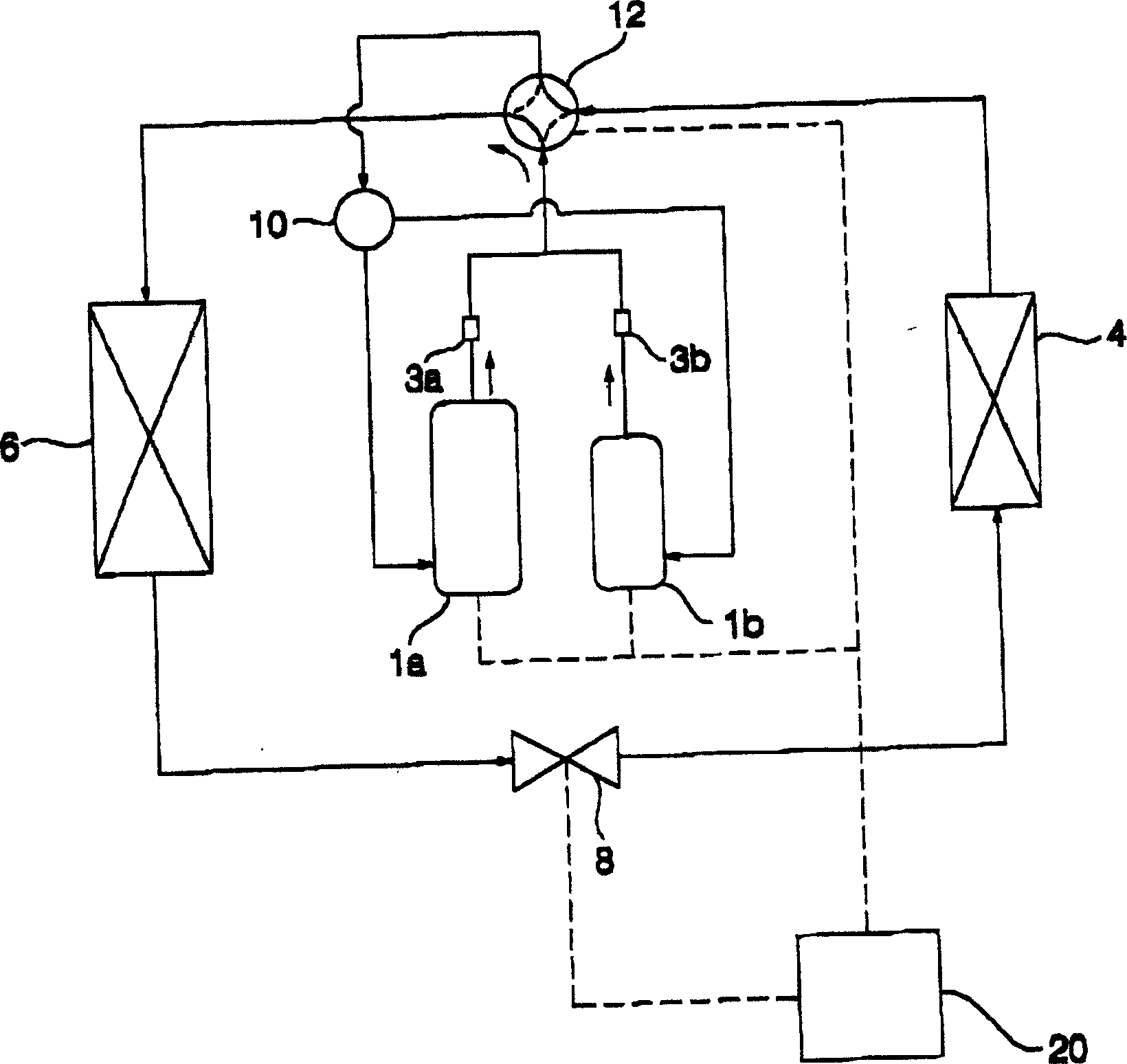
一种冷却循环、线性膨胀的技术,应用在具有可逆循环的压缩机器、机械设备、制冷和液化等方向,能够解决损坏压缩器1a和1b、压缩器1a和1b排放温度增加、冷却循环设备无法快速处理负荷等问题,达到防止排放温度过度增加、防止过热和损坏、优化冷却循环设备效率的效果

Inactive Publication Date: 2005-10-19
LG ELECTRONICS INC
View PDF0 Cites 15 Cited by
  • Summary
  • Abstract
  • Description
  • Claims
  • Application Information

AI Technical Summary

Problems solved by technology

As a result, the cooling cycle equipment cannot handle the load quickly when the pipe length is increased or the amount of refrigerant is insufficient
Also, the discharge temperature of the compressors 1a and 1b increases, thus damaging the compressors 1a and 1b

Method used


Image

  • Cooling cycle apparatus and method of controlling linear expansion valve of the same
  • Cooling cycle apparatus and method of controlling linear expansion valve of the same
  • Cooling cycle apparatus and method of controlling linear expansion valve of the same

Examples


Embodiment Construction

[0034] Now, preferred embodiments of the present invention will be specifically described with reference to the accompanying drawings. Although the same or similar units are shown in different drawings, they are denoted by the same reference numerals, and detailed descriptions thereof will be omitted.

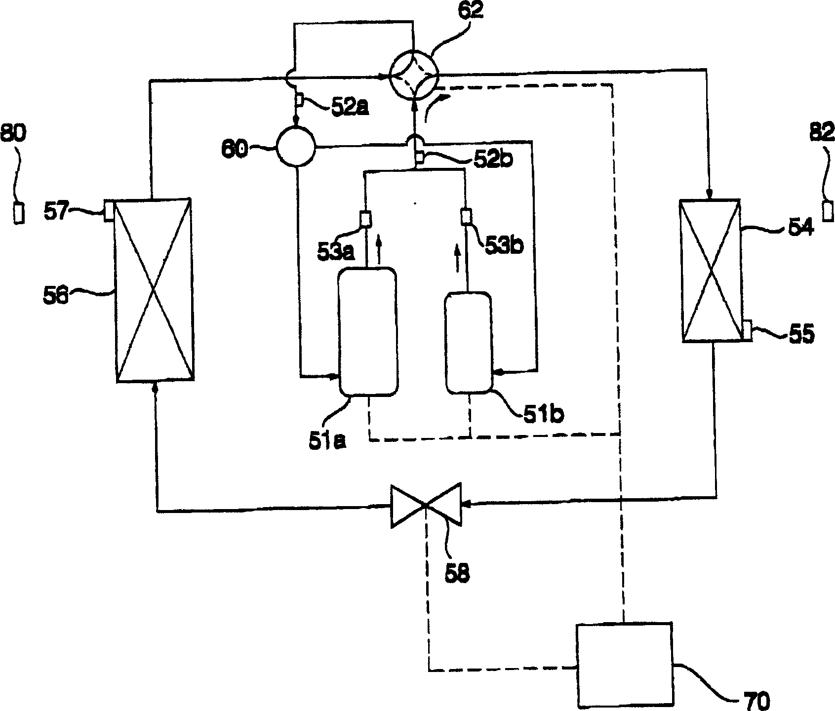
[0035] image 3 Is a circuit diagram showing the flow of refrigerant when the cooling cycle device according to the present invention is operated in the cooling operation mode, Figure 4 It is a circuit diagram showing the flow of refrigerant when the cooling cycle device according to the present invention is operated in the heating operation mode.

[0036] Such as image 3 with Figure 4 As shown, the cooling cycle equipment according to the present invention includes: a pair of compressors 51a and 51b for compressing a low-temperature and low-pressure gas refrigerant into a high-temperature and high-pressure gas refrigerant; an outdoor heat exchanger 54 for heating the refrigera...


PUM


Abstract

Disclosed herein is a method of controlling a linear expansion valve of a cooling cycle apparatus. The method comprises a first step of calculating a target opening level value according to suction overheat level of compressors to control a linear expansion valve based on the calculated target opening level value, and a second step of calculating a new target opening level value according to the suction overheat level of the compressors and discharge temperature of the compressors to control the linear expansion valve based on the calculated new target opening level value. Consequently, the discharge temperature of the compressors is prevented from being excessively increased, and therefore, the compressors are prevented from being overheated and damaged, and reliability of the cooling cycle apparatus is improved.

Description

Technical field [0001] The present invention relates to a cooling cycle device and a method for controlling its linear expansion valve, in particular to a cooling cycle device and such a method for controlling its linear expansion valve, the method can be based on the degree of compressor suction overheating To control the linear expansion valve, the cooling cycle equipment quickly handles the load, thus improving the reliability of the cooling cycle equipment. Background technique [0002] Generally, a cooling cycle device is a device that cools or heats the inside of a room where a specific component of the cooling cycle device is installed. The cooling cycle equipment includes a compressor, a condenser, an expansion mechanism and an evaporator. [0003] In recent years, multiple compressors have been installed in cooling cycle equipment, or linear compressors with variable compression capacity have been installed in cooling cycle equipment to properly operate the cooling cycle...

Claims


Application Information

Patent Timeline
Patent Type & Authority Applications(China)
IPC IPC(8): F25B41/06F25B13/00F25B49/02
CPCF25B13/00F25B49/02F25B2600/2513F25B2500/06F25B2700/21151F25B2700/21152F25B2313/0315F25B2400/075F25B2600/21F25B41/34F25B2341/06
Inventor 黄尹提金哲民崔昶民姜胜晫林亨洙
Owner LG ELECTRONICS INC
Learn More